14 Connecting Inlet Power, Input and Output Signals
3.5 Fuse Types and Locations
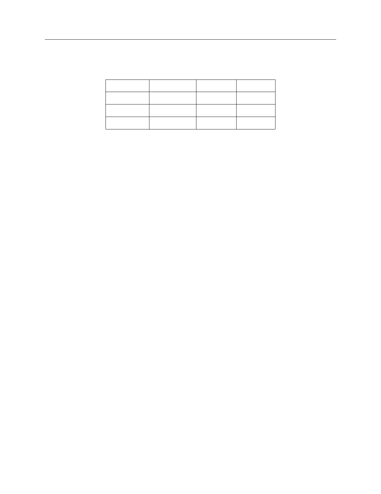
Use the fusing table below for identifying the correct fuse for your option power supply.
PS Option Arbiter PN Fuse ID Size, mm
07 FU0001816 F1AL250V 5 x 20
08 FU0001419 T2AL250V 5 x 20
10 FU0001816 F1AL250V 5 x 20
Table 3.2: Fuse Chart
3.5.1 Replacing Fuses
An IEC-320 power inlet connector includes a 1-A, 250-V fast acting fuse. The fuse is contained in
a small compartment with a snap-fit latch, which also has a compartment for a spare fuse. Check
Table 3.2 for replacement fuse information.
The fuse compartment is located directly adjacent to the input connector socket, and can be opened
by pulling both sides directly out away from the chassis, or by gently prying with a small flat-blade
screwdriver. To replace the fuse, first disconnect the line cord from the power source and then
remove the cord from the rear-panel IEC connector. The in-circuit fuse is the innermost one;
inspect it to determine if it is open. As required, replace with fuse in the outer compartment, and
replace the spent fuse.
With an Option 08 or 10, the input power module includes separate fuse holder adjacent to the
terminal power strip. See Table 3.2 above for the correct fuse configured for your option.
Option 08 and 10 fuses are located in a separate threaded compartment. To check the fuse, use a
small flat-bladed screwdriver and turn the cover counter-clockwise. The cover and fuse should pop
out. CAUTION: Replace fuse only with another of the same type and rating. See Table 3.2 above
for the correct fuse configured for your option.
To replace the fuse, first disconnect inlet power from the clock. Using a small flat-blade screwdriver,
turn the fuse cover counter-clockwise (CCW) and it should pop outward. Replace fuse with the
same size and type.
3.6 Connecting Output Signals
Output signals may be connected through designated standard BNC or option connector. For
standard I/O connectors, see Section 2.3.6. Connectors are standard female BNC. For Options
that have terminals for output connectors, see Appendix C for details about those options and
connectors. BNC connectors (on installed option boards) are female and require only connecting
the (male) connector into it.
3.7 Connecting Input Signals
Input signals may be connected through the designated I/O terminals, the RS-232 connector and
through an installed option connector designated as Input. For standard I/O connectors, see