10 Front and Rear Panels
2.3.4 RS-232 and RS-485 Communication Ports
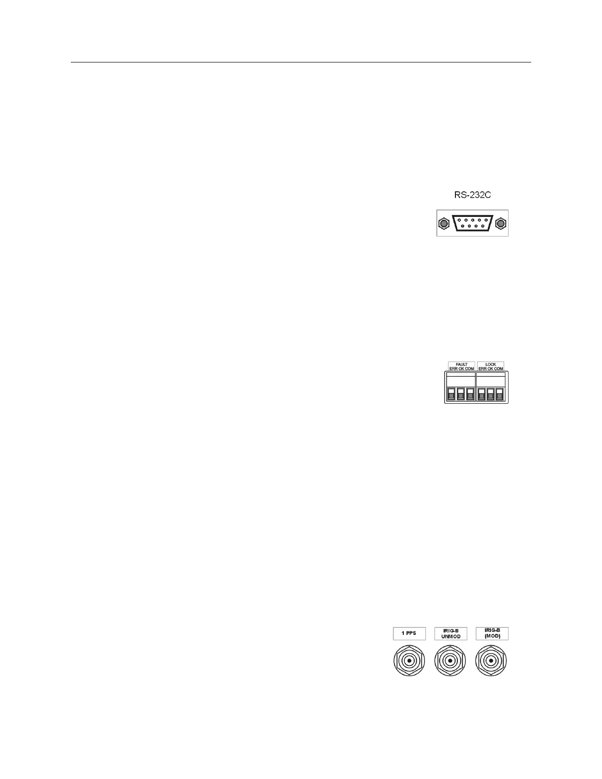
The Model 1084A/B/C have one standard and one optional communication port; the standard
with RS-232 and RS-485 supported, and the optional port with RS-232. The RS-232 port does not
use flow control and the RS-485 is transmit only (uses Transmit A and Transmit B, no Receive A
and Receive B). Generally, for RS-232 communications, you will only need pins 2, 3 and 5 using
a null-modem cable. For more information, see Chapter 9, Serial Communications and Command
Set.
Figure 2.7: Communications Port Connector
2.3.5 Form C, Relay Contacts
The Model 1084A/B/C has two sets of Form C relay contacts that have three contact points: ERR
(Normally Closed), OK (Normally Open) and COM (Common), where “Normally” refers to clock
powered OFF. For information on how to connect to them and their specifications, see Chapter 8,
Relay Contacts and Event Inputs.
Figure 2.8: Relay Contact Connectors
2.3.6 Standard Input/Outputs
The Model 1084A/B/C has three standard timing outputs for separate timing signals; when viewed
from left to right, 1 Pulse Per Second (PPS), unmodulated IRIG-B, and modulated IRIG-B. Out-
puts are as follows:
• IRIG-B modulated, bus driver, 4 Vpp, 20 ohms source impedance, drives a 50-ohm load at 3
Vpp.
• IRIG-B unmodulated or programmable pulse; jumper selectable
• IPPS, IRIG-B unmodulated or IRIG-B modified Manchester; jumper selectable
• Jumper-selectable outputs are 5 V CMOS bus drivers with 10 ohms source impedance and
±75 mA drive capability.
Single connectors may also be connected in parallel to drive multiple loads. For more information
concerning connecting timing signals, see Chapter 7, Timing, IRIG-B and Pulses.
Figure 2.9: Standard Input/Output Connec-
tors