6 Front and Rear Panels
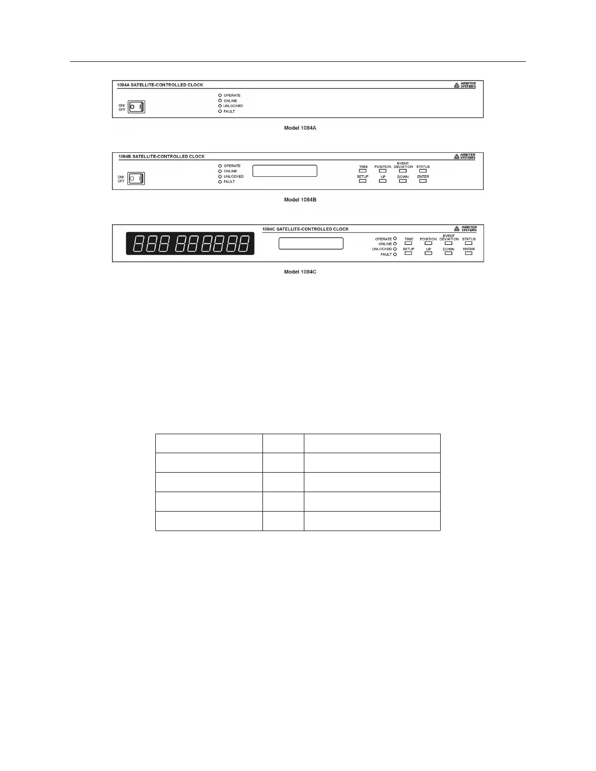
Figure 2.1: Model 1084A/B/C Front Panel Description
Definitions for the annunciator LEDs are found in Table 2.1 and definitions for keys in Table 2.2.
Each of upper row of keys allow you to view clock information, like time and date, geographical
position and instrument status. Each of the lower row of keys have specific and alternate functions
for configuring operation. To configure, see Chapter 6, The Setup Menus.
2.2.1 Annunciator LED Definitions
Annunciator LED Color Purpose
Operate Green Clock Operating
On Line Green Indicates Active Clock*
Unlocked Red Out-of-Lock when ON
Fault Red Internal/External Faults**
Table 2.1: Annunciator LED Definitions
* When used with Option 18, Redundant Interface, the On Line LED indicates which of the two
interconnected clocks is active.
** Illuminates when a fault condition exists with the clock or GPS receiver. See Table 10.1 for a
list of faults.
2.2.2 Command Key Definitions
Table 2.2 subdivides all of the functions of the eight keys by name and function. Some of the keys
have alternate functions as well.