20 GPS Antenna and Cable Information
4.2 Verifying Antenna and Cable Operation
A two-color operate LED, located at the base of the antenna, indicates proper antenna operation.
GREEN indicates proper operation (i.e. the antenna is getting the correct voltage); AMBER
indicates improper operation (i.e. the voltage is low).
4.2.1 Checking the Antenna Voltage
The GPS clock provides +5 Vdc to the GPS antenna, which is carried through the antenna cable.
Nominal antenna current is 13 mA. Check the voltage at the antenna connector on the rear panel.
Without the signal, the antenna and the GPS clock will not synchronize with the Global Positioning
System and can generate an out-of-lock alarm, if the Out-of-Lock feature is enabled.
4.2.2 Power Supply Check
The Antenna Voltage test (above) actually tests the main power supply voltage for all models of
clocks. This signal should be between 4.9 and 5.1 Vdc.
4.2.3 Checking the Antenna Resistance
Checking the internal resistance of the Arbiter GPS antenna is not as useful as verifying the antenna
operation mentioned above. Antenna resistance measures several megohms with meter probes at
one polarity and less so if you change the meter probe polarity.
4.3 GPS Surge Arrester
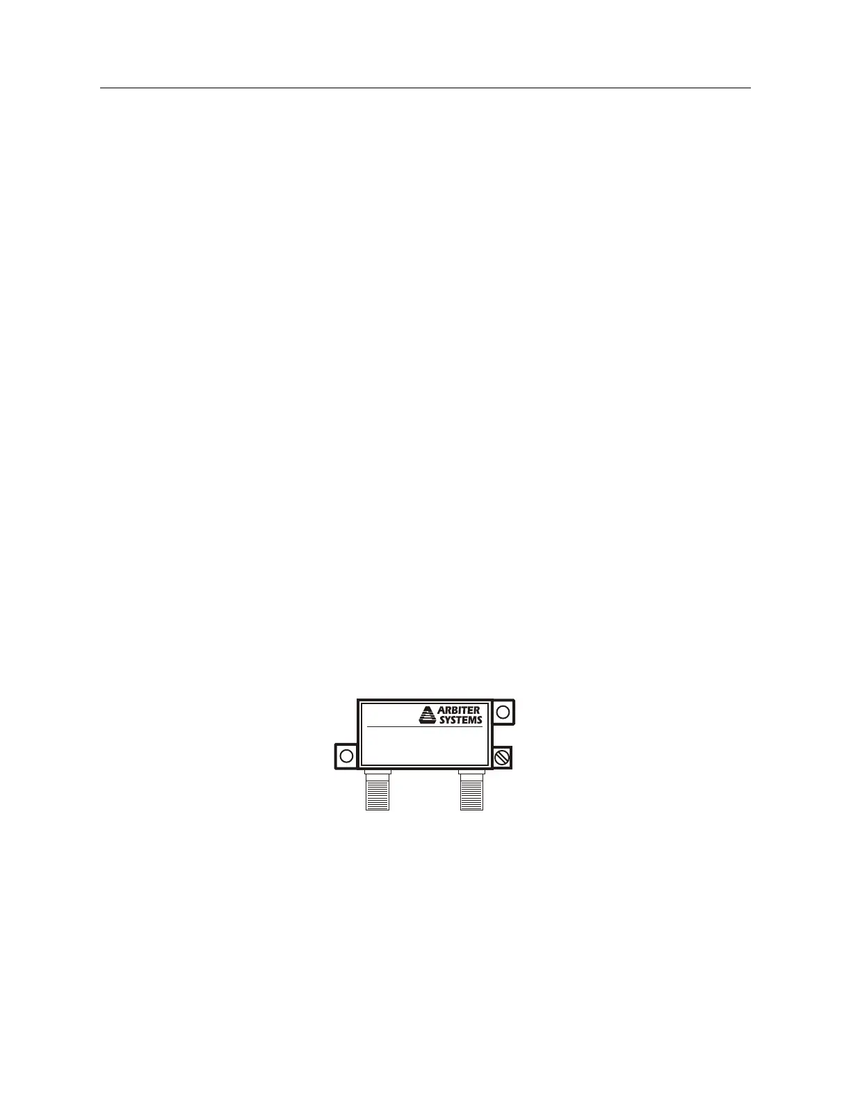
Figure 4.4 illustrates the GPS surge arrester kit (P/N AS0094500), which is mounted in line with
the antenna cable. The surge suppressor has two female F connectors, which are bidirectional, and
two ground lugs with hardware for connecting to a solid ground.
Antenna
Receiver
Surge Arrester/Grounding Block
AS0094500A
Figure 4.4: GPS Surge Arrester
4.3.1 Using the GPS Surge Arrester
Before installation, review the documentation on this device found in Appendix B. The AS0094500
surge arrester is weatherproof except for the F connectors, which may be sealed with rubber port
seals or GE Silicone II compound.