C.17 Option 29: Four Additional Outputs; Dry Contacts; +25/50 Vdc 169
C.17.4 Output Jumper Setting Changes
1. Set Line Power switch to OFF position (if equipped). Disconnect the power cord from rear-
panel.
2. Remove rack-mount ears (if equipped) and remove top cover using a T25 Torx driver.
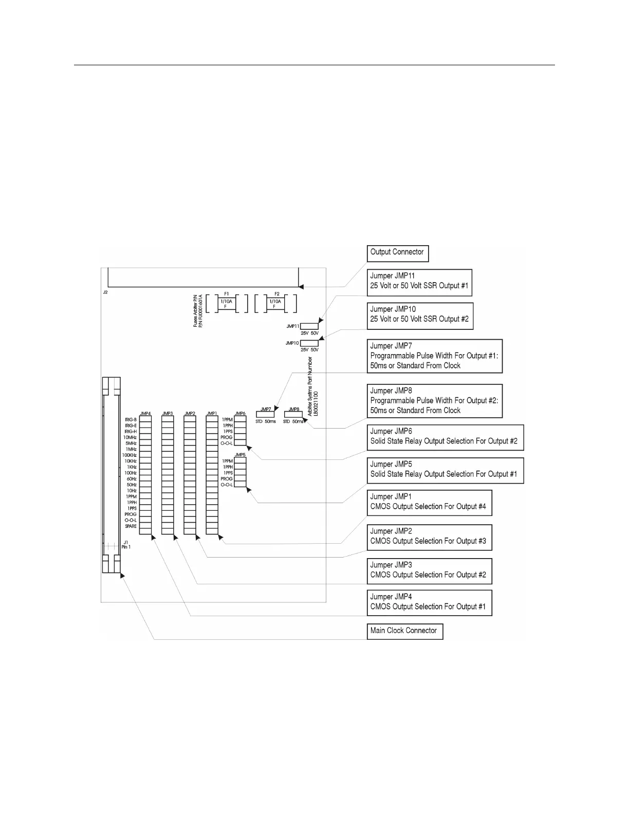
3. Locate the appropriate Jumper using Figure C.19 and move the jumper to the desired setting.
4. Replace the top cover and rack-mount ears (if equipped).
5. Connect the power cord to the rear-panel and power the clock ON.
Figure C.19: Option 29 Jumper Locations