2.3 Rear Panel Identification and Connectors 9
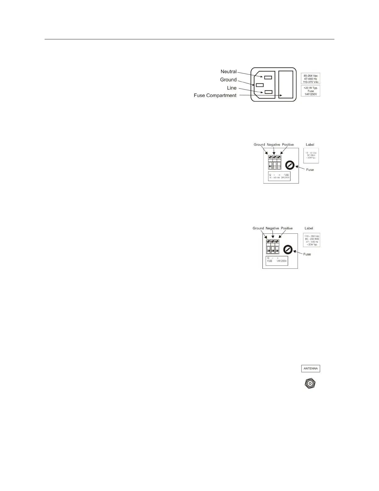
• Option 07, IEC-320 supply with a range of 86 to 264 Vac, 47 to 440 Hz and 110 to 370 Vdc
Figure 2.3: Option 07 Power Supply Inlet
Connector
• Option 08, 10 to 60 Vdc ONLY, Terminal Power Strip with Surge Withstand Protect Circuitry
(SWC) power
Figure 2.4: Option 08 Power Supply Inlet
Connector
• Option 10, 110 to 350 Vdc and 85 to 250 Vac, 47 to 440 Hz, Terminal Power Strip with Surge
Withstand Protect Circuitry (SWC)
Figure 2.5: Option 10 Power Supply Inlet
Connector
2.3.2 Antenna Input
The Model 1084A/B/C provides a type-F, GPS antenna input connector not only as the connection
point for GPS signal, but also supplies 5 volts to energize the antenna. It is equipped with a
threaded, type-F female connector.
Shown below is a diagram of the antenna connector. To check for this signal, use a small multimeter
and probe from the center pin of the connector to the threads. Voltage range is 4.9 to 5.1 Vdc. For
further information, see Chapter 4, Antenna and Cable Information.
Figure 2.6: GPS Antenna Connector
2.3.3 Event Input
For timing external events based on the GPS-synchronized time, use the Event Input function with
two separate connectors: P3 (Standard I/O) and J2 (RS-232C). See Figure 5.1, which illustrates
the location of these connectors and jumpers.