i2000SR interface module Service Manual
Page 104 of 212 625798100.APS.5.doc
STEPS REFERENCES
14 Disconnect the three connectors of
the orange cables shown in the figure
and remove the cable supports from
assembly.
The gray and maroon wires will be
not disconnected. Their length will
control the distance that the two
sections can be separated.
15 Raise the 2nd line belt to access the
screws shown in the figure and
remove them to separate Lane 1-2
section from Lane 3-4 section.
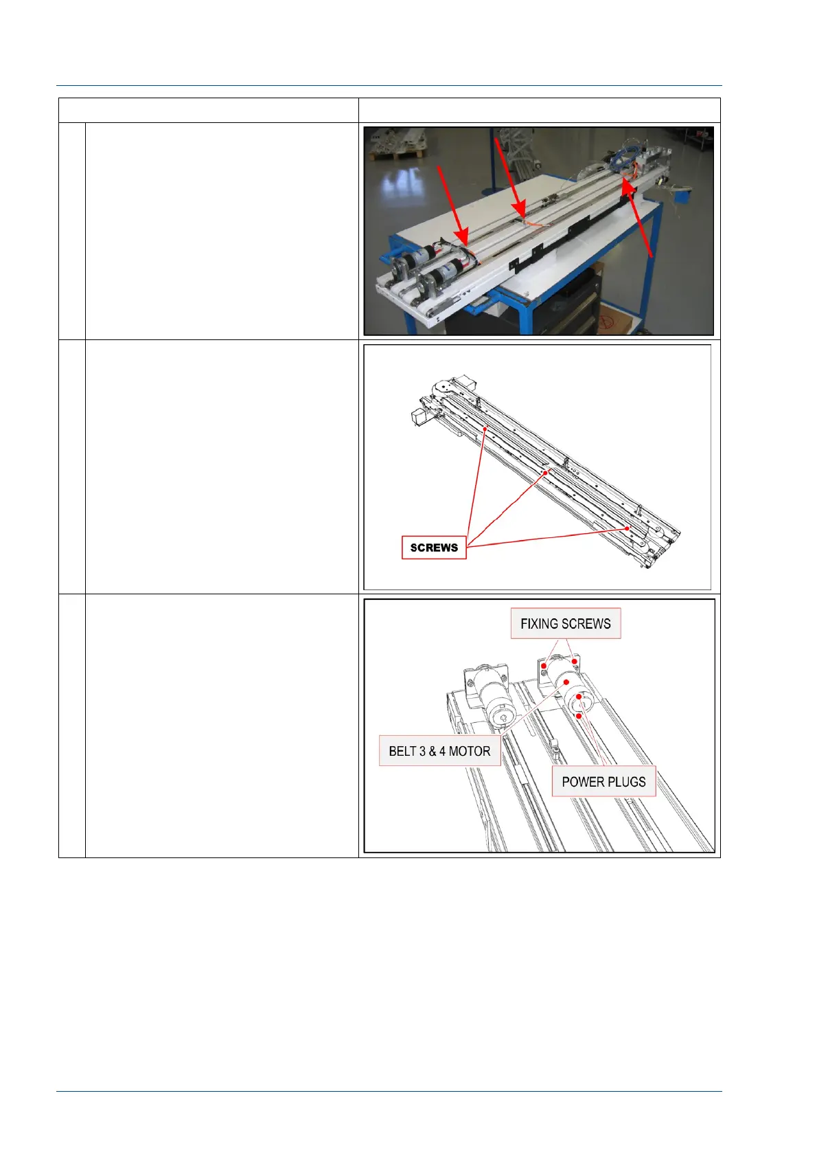
16 Remove the Belt 3 & 4 motor.