Service Manual i2000SR interface module
625798100.APS.5.doc Page 105 of 212
STEPS REFERENCES
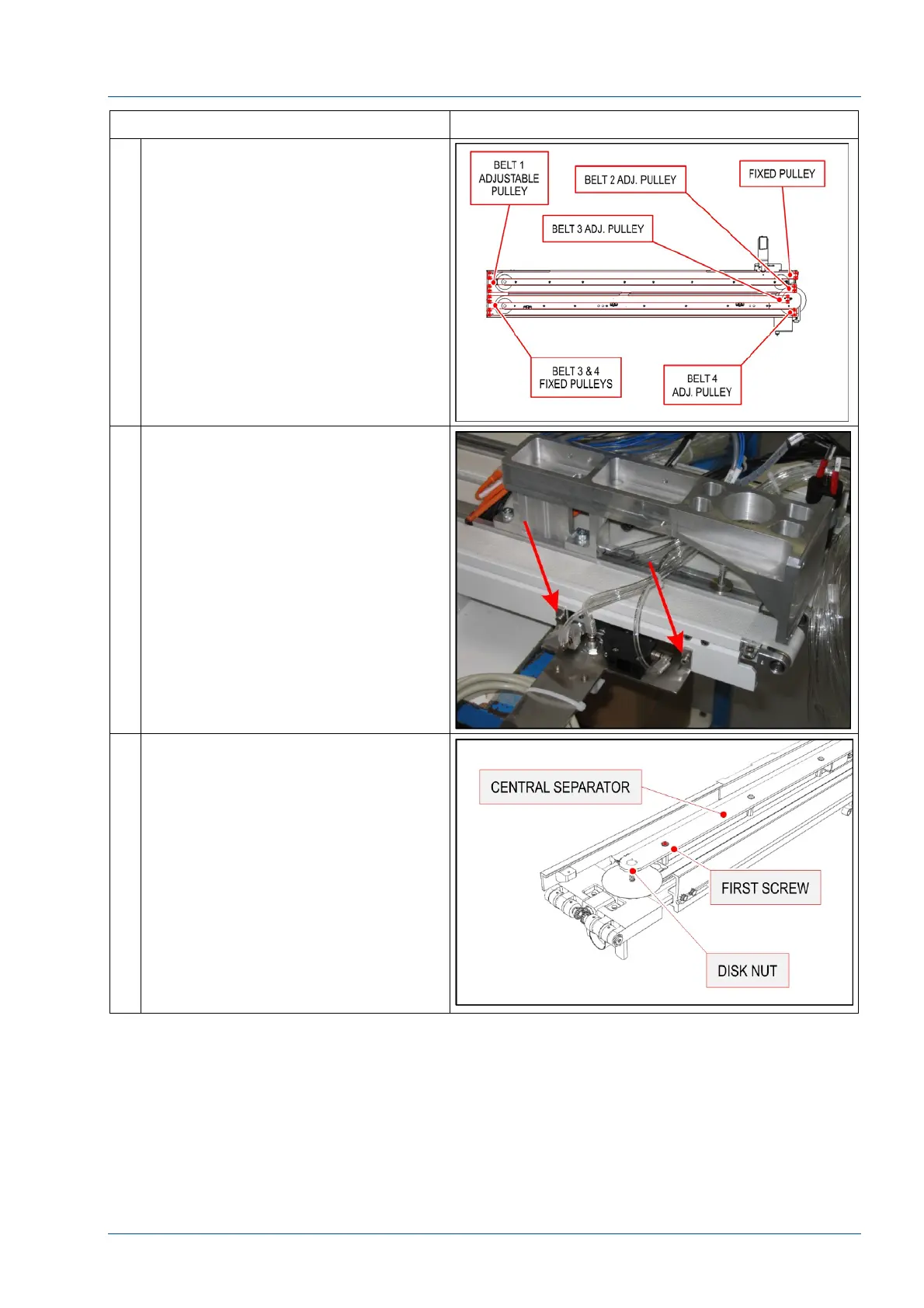
17 Refer to the figure for terminology
used in this procedure.
The correct belt tensioning order is:
Belt 1 – 2 – 3 – 4
18 Belt 1 Replacement – PFD0304
Remove the pneumatic multi
connector bracket to access the
screws shown in the figure.
Starting from the Lane 1-2 section,
remove the screws shown in the
figure to remove the barcode reader
bracket.
19 Loosen the first screw of the central
separator to avoid interference with
the disk rotation nut.