i2000SR interface module Service Manual
Page 106 of 212 625798100.APS.5.doc
STEPS REFERENCES
20 Remove the screws indicated in the
figure to remove tension from the
belt of Lane 1 and replace it.
21 Belt 1 Tensioning
Install the new belt and use the
screws shown in the figure to apply
tension to the belt of Lane 1.
Follow the
Verification of belt
tensioning
procedure to verify the
belt tension.
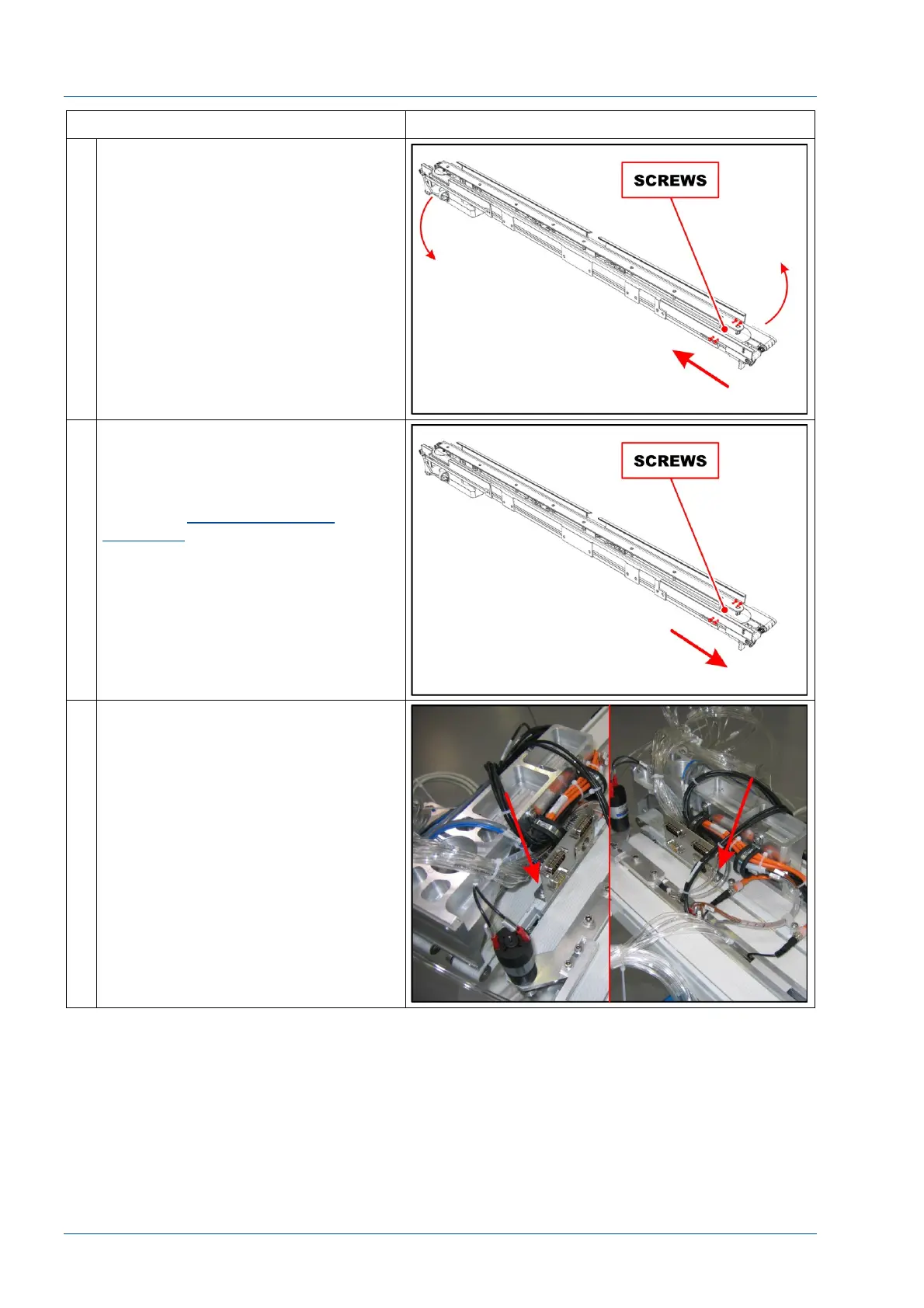
22 Belt 2 Replacement – PFD0302
Remove the two screws shown in the
figure to remove the connector panel.