i2000SR interface module Service Manual
Page 16 of 212 625798100.APS.5.doc
into an empty carrier at this time. When the LED is green, tubes
can be manually loaded into the carrier located at this gate.
Gate 7a – (G7a) is on Lane 2 and is operated by electro valve
EV10. This Type 1 gate stops the carrier on Lane 2 to avoid a
collision with a carrier that is being introduced from the Lane 3
Routine Manual input area gate (G7b). The Routine Manual Input
samples from Lane 3 have precedence over carriers running on
Lane 2. The opening of the diverter D1 (Lane 3/2 Diverter) drives
the closing of Gate 7a and prevents collisions as a new tube
carrier enters from the manual input gate. (See Gate 7b).
Gate 8 (G8) – is the Priority Input Gate located on Lane 3 and is
operated by electro valve EV16. This Type 2 gate is located at the
Priority Manual Input position and is controlled by an optical tube
sensor located at the entry position. The sensor is used to verify
the presence of a tube in the carrier. The Priority Input position is
used to insert priority samples, calibrators and controls. The
carrier will be introduced onto the large disk and routed via the
pair of D2 diverters to Lane 1. The D2 diverters are the Lane 3/1
and Lane 2/1 Diverters and are operated by electro valve EV4.
The Lane 3/1 Diverter is positioned to prevent the carrier from
being routed to the Main APS track. The Lane 2/1 Diverter opens
to allow the carrier to enter Lane 1.
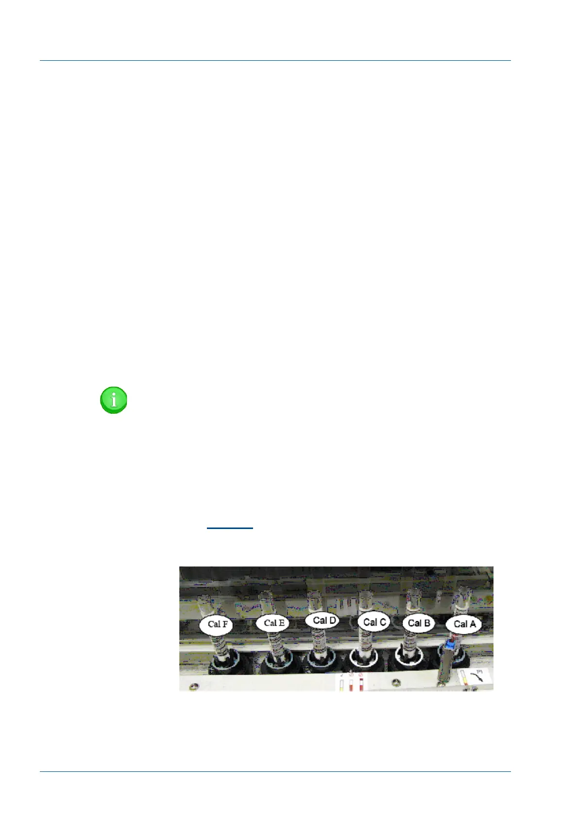
NOTE:
When introducing calibrators and other tubes that need to
be processed according to a specific order, they must be
loaded in order at the Priority Input queue. The last
calibrator to be processed is placed into the appropriate
carrier to the left of the entry point. For a six (6)-point
calibration, the last calibrator “F” is loaded into sixth
carrier to the left. The remaining calibrators are loaded in
sequence as illustrated below. The first calibrator to be
aspirated is “A” and is loaded at the Priority Entry point.
(See
Figure 5
) When the first tube is detected the entire
set of tubes will move in to be processed.
Figure 5 – Calibrator Load (Six point)
Gate 9 (G9) – This Type 1 gate is located on the APS main track
and is operated by electro valve EV17. An optical sensor is
positioned to detect that the On-line carrier was routed from the
large disk and was returned to the main track. The optical carrier