Home
Architect
Measuring Instruments
i2000SR
Page 162
Architect i2000SR - Page 162
212 pages
Manual
Save Page as PDF
To Next Page
To Next Page
To Previous Page
To Previous Page
Loading...
i2000SR interface module
Service Manual
Page 162 of 212
625798100.APS.5.doc
STEPS REFERENCES
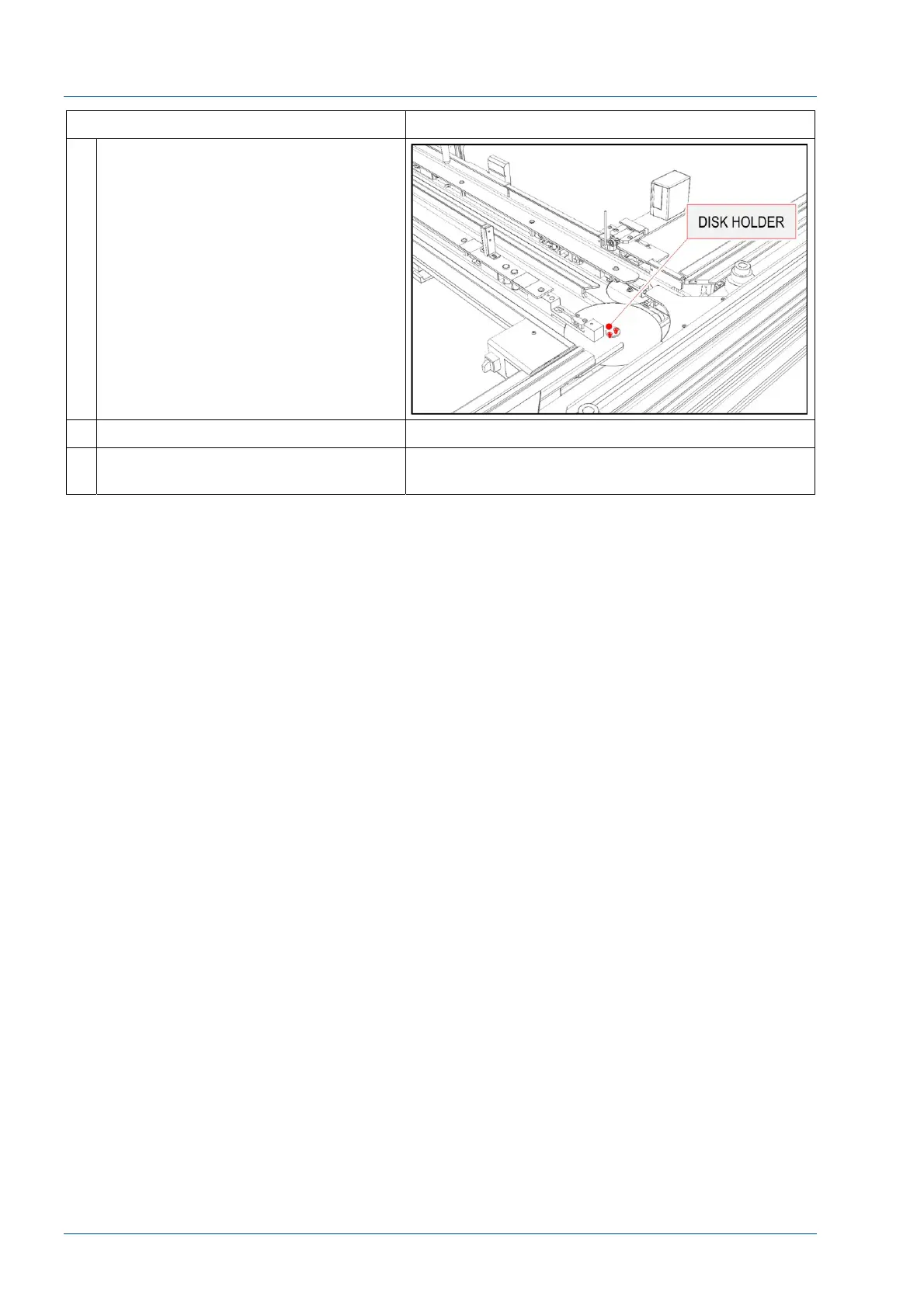
9
Remove the two screws to remove
the disk holder and disk.
10
Install a new disk.
11
Perform the steps above in reverse
order to reassemble the i2000SR IM.
161
163
Table of Contents
Main Page
Default Chapter
2
Table of Contents
2
Overview
4
Identification Data
4
Warnings Concerning Safety
4
Laser Safety
5
Description
7
Tube Lanes
9
Input and Output Areas
10
Path of the APS Carriers
10
Path of the I2000Sr IM Carriers
11
Input and Output Areas
11
Process Controls
12
Stop Gates
12
Brief Description of the Stop Gate Devices
13
Off-Line Carriers
15
On-Line Carriers
15
Diverters Description
17
IM Antenna and Optical Sensors
19
I2000Sr Instrument Indicator Light (IM Pole Lamps) Functioning
20
RED LAMP ON: Error or Initializing
20
RED LAMP Blinking: SCC CLI Communication Error
20
YELLOW LAMP Blinking
20
GREEN LAMP ON: Running, Paused or Pausing
21
Modes of Operation
21
I2000Sr IM Pneumatics Components
23
I2000Sr IM Electrical Components
25
MASTER CAN Board Description
26
MASTER CAN Board Segment Indicator
28
SLAVE 0 CAN Board Description
28
SLAVE 0 CAN Board Segment Indicator
29
SLAVE 1 CAN Board Description
29
SLAVE 1 CAN Board Segment Indicator
31
Electrical Panel Connectors
32
I2000Sr IM Electrical Box Startup
34
Starting I2000Sr IM in APS Mode
35
Starting I2000Sr IM in Standalone Mode
36
I2000Sr IM Track Initialization
37
Rebuilding Queues
38
Standalone Mode Initializing
38
APS Mode Initializing
38
I2000Sr IM Exercise Mode
38
Instructions for Assembly
40
I2000Sr IM Parts Shipped
40
Parts Shipped for a New Installation
41
Parts Shipped for a Retrofit Installation
41
The 21 I2000Sr IM Off-Line Carriers
41
Assembly Procedure
42
Prerequisite
42
Installation of the Instrument Indicator Light (Pole Lamps)
42
Installation of the I2000Sr IM
43
Pneumatic Connections
49
Initial I2000Sr Support Procedure
50
Electrical Connections
53
IM Track Interface Cable Connections
54
IM Electrical Box Cable Connections
54
I2000Sr Ground Wire Installation
56
AC Power Connections
57
I2000Sr IM LUI Panel Installation Procedure
58
I2000Sr / I2000Sr IM Alignment Procedure
60
I2000Sr IM Horizontal Positioning Check
65
I2000Sr IM Vertical Positioning Check
66
Alignment of Routine and STAT Sampling Probes, Gates and Antennae
68
Install the Gap Filler
68
Install 7L46-01 Off-Line Carriers
70
Initialize I2000Sr IM
71
Verify Config Wizard I2000Sr Setting
73
Modify Config Wizard for I2000Sr
73
Modify Instrument Queue for Instrument Following I2000Sr
76
Modify Instrument Setup.ini File
77
Exercise I2000Sr IM
78
Verify Carriers Movement from the APS Track to I2000Sr IM
80
Complete Installation of I2000Sr las
82
Retrofit of the I/O Module Pneumatic Panel and Circuit
83
IOM Pneumatic Panel Differences
86
Replacement Procedures
88
Replacement of I2000Sr IM
88
Replacement of I2000Sr IM Belts
100
Replacement of Light Pole Lamp
111
Replacement of Belts Motor
115
Replacement of Motor Belt Group
120
Replacement of Disk Motor
126
Replacement of Belts 1 & 2 Drive Group
132
Replacement of Belts 1 & 2 Idler Pulleys Groups
137
Replacement of Belts 3 & 4 Drive Group
141
Replacement of Belts 3 & 4 Idler Pulleys Groups
145
Replacement of I2000Sr IM Antennas
149
Replacement of Belt Disk
154
Replacement of the Big Belt Disk
159
Replacement of the Carrier Spinning Group
164
Auxiliary Procedures
170
Alignment of Barcode Reader
170
Alignment of Routine and STAT Sampling Gates
176
Sample and STAT Antennae Alignment Verification Procedure
182
Antennas Test Procedure
187
Verification of Belt Tensioning
191
Verification of Carrier Routing
194
Tag Reader CAN BUS Board Firmware Installation
198
Preventive Maintenance Procedures
203
Lubrication of Gears
203
Spare Parts List
208
I2000Sr IM Part List
208