i2000SR interface module Service Manual
Page 184 of 212 625798100.APS.5.doc
STEPS REFERENCES
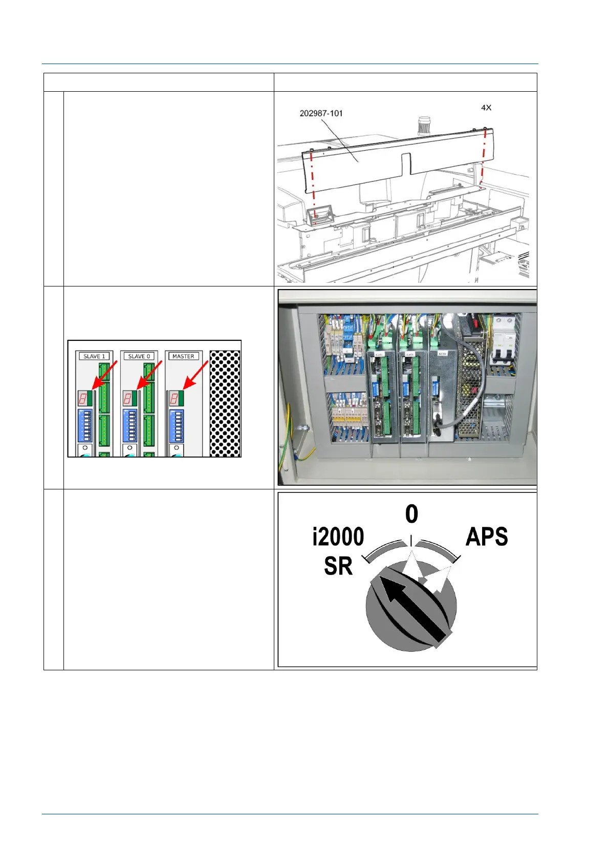
2 Remove the center cover by loosening
the four (4) ¼ turn screws.
3 Open the front panel of the i2000SR IM
electrical box and locate the MASTER,
SLAVE 0, and SLAVE 1 CAN-BUS board
7-segments red displays.
4 Switch on the i2000SR IM in
standalone mode. (Power switch in
“i2000 SR” position).