Service Manual i2000SR interface module
625798100.APS.5.doc Page 51 of 212
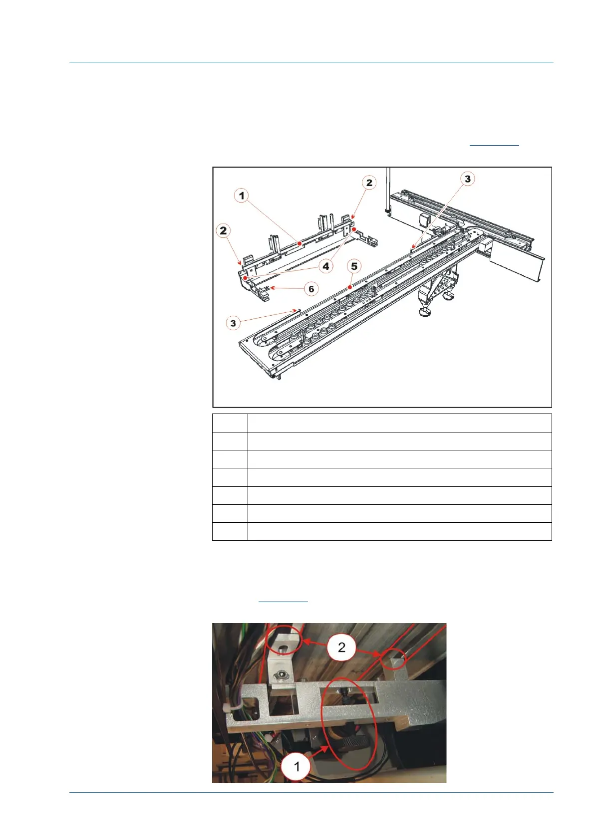
• Move the i2000SR with the LAS support bracket installed,
under the i2000SR IM.
• With the i2000SR pulled forward, ensure the two tabs on
the i2000SR bracket [2] are centered between the corresponding
notches on the instrument side of Lane 1 [3]. (See
Figure 28
).
Figure 28 – Positioning i2000SR instrument
No. Description
1 i2000SR insert spur rail
2 i2000SR insert spur rail cut-off
3 i2000SR IM assembly cut-out extreme limits
4 i2000SR slider spur supports
5 i2000SR IM assembly cut-out
6 i2000SR bracket attachment
• At the i2000SR LAS support bracket, adjust the two
knurled knobs [1] in a manner that applies support to the i2000SR
IM. (See
Figure 29
)
Figure 29 – i2000SR Support Bracket