3-15
3
PR388
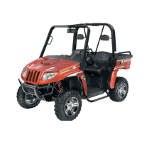
5. Remove the fixed drive face.
6. Using an impact driver, remove the cap screws
securing the air intake plate; then remove the
plate cushion.
PR393
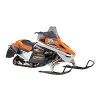
7. Remove the cap screws securing the clutch
cover. Note the location of the differ-
ent-lengthed cap screws for installing purposes.
Using a rubber mallet, carefully remove the
cover. Account for two alignment pins.
CD973A
CD974A
NOTE: For steps 8-14, refer to illustration
CC829B.
NOTE: To aid in installing, it is recommended that
the assemblies are kept together and IN ORDER.
CC829B
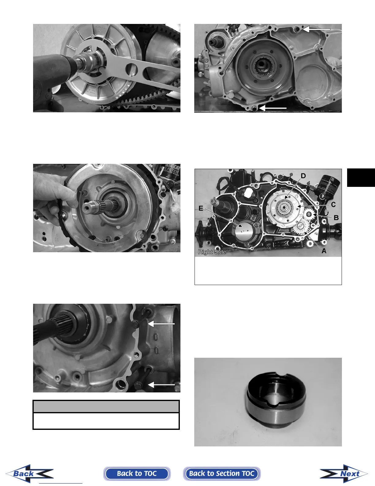
8. Remove the one-way clutch (D) from the clutch
housing. Note the location of the green dot (or
the word OUTSIDE) for installing purposes.
9. Using a hydraulic press, remove the clutch hous-
ing assembly from the clutch cover. Account for
the left fixed drive spacer and an O-ring inside
the fixed drive spacer.
CF085
! CAUTION
Care must be taken when removing the cover so the
cover gasket is not damaged.
KEY
A. Oil Pump Driven Gear
B. Oil Pump Drive Gear
C. Clutch Shoe Assembly
D. One-Way Clutch
(Green Dot MUST Show)
E. Final Drive Carrier Bearing
Housing
Back to TOC
Back to Section TOC
Next
Back
FOR ARCTIC CAT ATV DISCOUNT PARTS CALL 606-678-9623 OR 606-561-4983
www.mymowerparts.com