3-47
3
5. Install the coolant hose onto the crankcase union
and tighten the clamp.
C. Cylinder Head
D. Valve Cover
0741-101
NOTE: Steps 1-5 in the preceding sub-section
must precede this procedure.
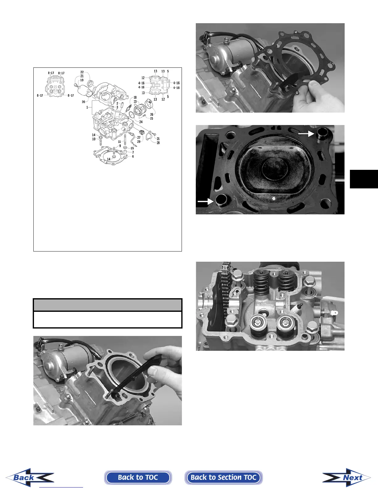
6. Place the chain guide into the cylinder.
CC022D
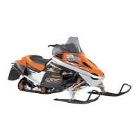
7. Place the head gasket into position on the cylin-
der. Place the alignment pins into position; then
place the head assembly into position on the cyl-
inder.
CC020D
CF057A
8. Install the four cylinder head cap screws with
copper washers (note the locations of the differ-
ent-lengthed cap screws). Tighten only until
snug.
CC272D
9. Loosely install the five cylinder head nuts.
10. In a crisscross pattern, tighten the four cylinder
head cap screws (from step 8) to 5.5 kg-m (40
ft-lb); then tighten the 8 mm nut (from step 9) to
2.5 kg-m (18 ft-lb). Using a crisscross pattern,
tighten the 6 mm nuts (from step 9) to 1.1 kg-m
(8 ft-lb). Tighten the two cylinder-to-crankcase
nuts (from step 4) securely.
11. With the timing inspection plug removed and
the chain held tight, rotate the crankshaft until
the piston is at top-dead-center.
! CAUTION
Care should be taken that the bottom of the chain
guide is secured in the crankcase boss.
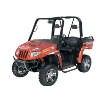
KEY
1. Cylinder Head
Assy
2. Valve Guide
3. Dowel
4. Cap Screw
5. Cap Screw
6. Cylinder Head
Gasket
7. Pin
8. Cap Screw
9. Stud Bolt
10. Stud Bolt
11. Stud Bolt
12. Cap Screw
13. Cap Screw
14. Nut
15. Nut
16. Gasket
17. Crush Washer
18. Spark Plug
19. Inspection Cap
20. O-Ring
21. Cap Screw
22. Cylinder Head
Plug
23. Intake Pipe
Assy
24. O-Ring
25. Machine Screw
26. Clamp
27. Temperature
Switch Assy
28. Thermostat
Cover
29. Thermostat
*Frost Plug
*Not Illustrated
Back to TOC
Back to Section TOC
Next
Back
FOR ARCTIC CAT ATV DISCOUNT PARTS CALL 606-678-9623 OR 606-561-4983
www.mymowerparts.com