6-17
PPC Manual Revision 1
n
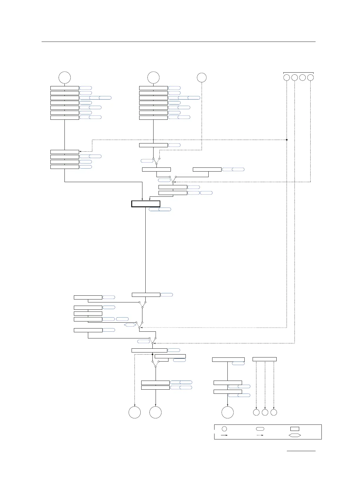
Loop Control with PV-hold Function Function Block Diagram
Target setpoints 1 to 8
COM
Aux. input
*1
Output limiter
Manual operation
Manual preset output
Input error preset output
Preset output
STOP (ON)/RUN (OFF) switch
LOCALREMOTE
AUTO
When sensor burnout occurs
Normal
MAN
RUNSTOP
SP ramp rate
SP limiter
DI16PV RSP
Input type
Input unit
Input range/scale
Analog input bias
Square root extraction
Analog input filter
Input type
Input unit
Input range/scale
Analog input bias
Square root extraction
Analog input filter
10-seg. linearizer approx./bias
Remote input filter
PV input bias
PV input filter
Ratio bias computation
Output limiter
A.BS
A.FL
BS
PV-hold function
FL
PMD An, Bn
10-seg. linearizer approx./bias
PMD An, Bn
10-seg. linearizer approx./bias
PMD An, Bn
CNT ALG
UPR, DNR TMU
SPNO SP
R/L
RMS
SPH, SPL
RFL
A.SR A.LC
UNIT
IN
RH, RL SDP SH, SL
A.BS
A.FL
A.SR A.LC
UNIT
IN
RH, RL SDP SH, SL
EPO
OH, OL
OH, OL OLMT
PO
S/R
MPON
OT
(Current when retransmission output)
Current or
voltage pulse
Relay Current
OUTOUT RET AL3AL2AL1
PMD
OU.H OU.L
An, Bn
Split computation
10-seg. linearizer approx./bias
RET.H RET.L
PMD An, Bn
Split computation
10-seg. linearizer approx./bias
OUT retransmission output
O1RS
RET retransmission output
RTS
Alarm
Output terminal assignment
DI3DI2DI1
A/M
REMOTE (ON)/LOCAL (OFF) switch
AUTO (OFF)/PV holde, MAN (ON) switch
Control computation
AUTO (ON)/PV hold, MAN (OFF) switch
No function
is assigned
to DI3.
PV input
Remote auxiliary analog
input (if equipped)
Contact inputs
* After the control output terminal is specified by the parameter OT,
other current output terminals can be used as retransmission output.
Terminal Parameter Function
Analog signal Contact signal Front panel key
Legend
Alarm 1
(PV high limit)
Alarm 2
(PV low limit)
Alarm 3
(PV high limit)
PV display
SP display
Communication
*1: RS-485, Ethernet (if equipped)
DI16 is equipped on models with
remote auxiliary analog input RSP
Chapter 6: Control Mode Settings

 Loading...

