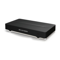
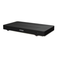
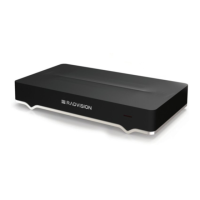
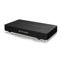
• Connect one end of the USB cable to the USB socket on the Scopia
®
XT Camera Switch
and the other end to the upper USB connector on the XT Codec Unit. This cable also
provides power to the device, so no extra power cable is required.
Figure 30: Connecting the Scopia
®
XT Camera Switch to the XT Codec Unit
3. Insert the three connectors of the camera cable (3 connectors on one side, 2 connectors on
the other side) to the sockets on the back of the camera, as shown in
Figure 26: Connecting
cables to the back of the camera on page 50:
• The DVI connector to the DVI socket
• The 8-pin connector to the IN RS232C socket
• The power connector to the DC IN 12V socket
Figure 31: Connecting cables to the back of the camera
Connecting Cameras or DVD players
April 2015 Avaya Scopia
®
XT Series Deployment Guide 55
Comments? infodev@avaya.com

 Loading...


