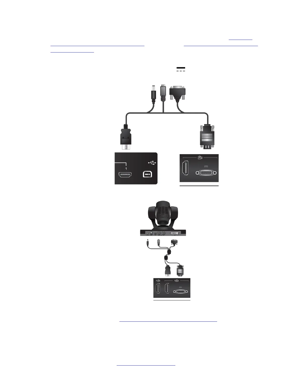
4. Attach the two connectors on the other end of the camera cable as shown in Figure 32:
Connecting cables to the XT5000 Series on page 56 and Figure 33: Connecting cables to
the XT7000 Series on page 56:
a. The HDMI connector to the HDMI socket labeled 1 on the Scopia
®
XT Camera Switch.
b.
The connector for power and serial control to the
horizontal HDMI socket on the XT
Codec Unit.
Figure 32: Connecting cables to the XT5000 Series
Figure 33: Connecting cables to the XT7000 Series
5. Connect the second camera (
Figure 34: Connecting the second camera on page 57):
a. Connect the 10-meter VISCA crossed cable supplied with the camera kit.
Setting Up the XT Series Hardware
56 Avaya Scopia
®
XT Series Deployment Guide April 2015
Comments? infodev@avaya.com

 Loading...


