5.
Locate the memory map setup from Banner module to PLC memory map.
C = Configuration (not used)
I = Inputs to PLC (outputs from iVu Plus)
O = Outputs from PLC (inputs to iVu Plus)
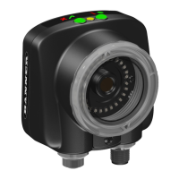
iVu Plus TG Gen2 Image Sensor
www.bannerengineering.com - Tel: 763.544.3164 127

 Loading...