DECS-200 BESTCOMS Software 5-19
Field Current Step Response, Increment of FCR Setpoint.
Sets the current step size that the DECS-200
uses when incrementing the field current setpoint. A setting of 0 to 10% may be entered in 1%
increments. A button adjacent to this setting is clicked to increment the field current setpoint. A read-only
field indicates the field current setpoint that will be achieved when the increment button is clicked. If the
specified step size is outside the setpoint limit, a warning message will appear.
Field Current Step Response, FCR Setpoint.
This read-only field indicates the field current setpoint that
was set on the AVR/FCR tab of the Setting Adjustments screen. A button adjacent to this field is clicked
to return the AVR setpoint to the displayed value.
Field Current Step Response, Decrement of FCR Setpoint.
Sets the field current step size that the DECS-
200 uses when decrementing the field current setpoint. A setting of 0 to 10% may be entered in 1%
increments. A button adjacent to this setting is clicked to decrement the field current setpoint. A read-only
field indicates the field current setpoint that will be achieved when the decrement button is clicked.
Field Current Step Response, Ifd.
This read-only field indicates the value of field current. The other three
fields are described in the corresponding tab setting descriptions.
Alarm Signals.
During step response analysis, nine alarm indicators are available to indicate system
alarms. A list of the indicators is provided under
Analysis, AVR
. Alarm annunciations are updated
approximately once every second.
Var
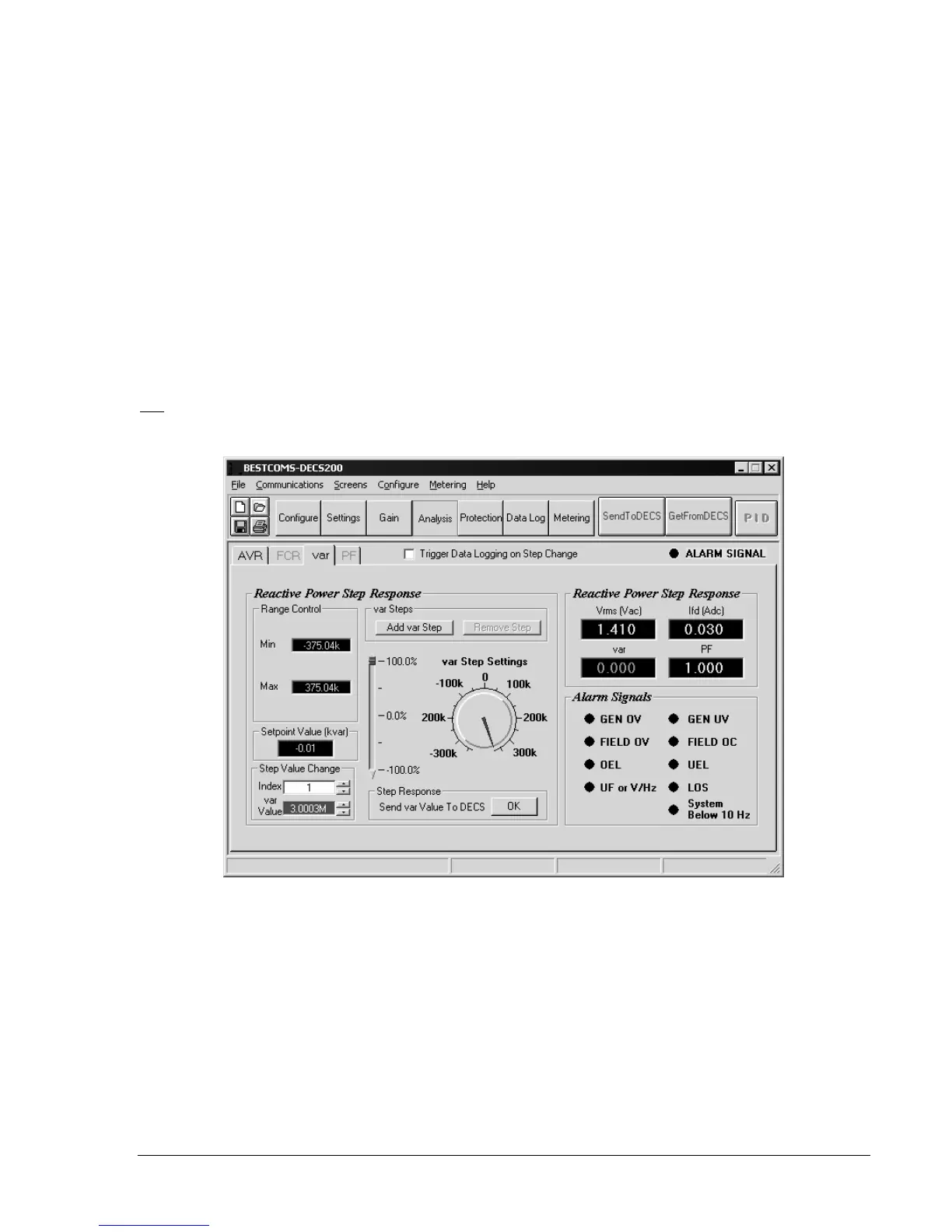
Var tab settings are illustrated in Figure 5-23 and described in the following paragraphs.
Figure 5-23. Analysis Screen, var Tab
Reactive Power Step Response, Range Control, Min.
Changes the range indicated by the var Step
Settings dial and the minimum allowable var settings for the generator. To change the minimum dial
value, double-click the field value, enter a new minimum limit, and press the Enter key.
Reactive Power Step Response, Range Control, Max.
Changes the range indicated by the var Step
Settings dial and the minimum allowable var settings for the generator. To change the maximum dial
value, double-click the field value, enter a new minimum limit, and press the Enter key.
Reactive Power Step Response, Setpoint Value.
This read-only field indicates the reactive power setpoint
established on the var/PF tab of the Setting Adjustments screen. If a step-response setpoint change has
been made from this screen, the actual setpoint value for the regulator will differ from this read-only
indication.
Reactive Power Step Response, Step Value Change var Value.
Provides one of three methods for
changing the kvar setpoint and observing the generator response. (The other two methods include