5-20 BESTCOMS Software DECS-200
adjusting the var Step Settings dial or slide bar.) Once the desired value is entered, the value is sent to
the DECS-200 by clicking the Send var Value to DECS (OK) button. When clicked and held, the button
color changes to red and the button label changes to “Index 1”. Upon release of the button, the new var
value setting is sent to the DECS-200 as the reactive power setpoint for the var regulator. If the specified
var value is outside the range limit, a dialog box appears and shows the acceptable values for the step
response. Changing the var setpoint through the var Value field does not change the dial or slide
indicators.
The pointer of the var Step Settings dial can be clicked and dragged to the approximate, desired setting.
As the pointer is dragged, the slide bar moves to show the relative percentage of the minimum or
maximum var setting. The setpoint can then be fine tuned using the up and down scrolling buttons of the
var Value window.
Reactive Power Step Response, Step Value Change Index.
Up to three var step-response setpoints
(indexes) can be activated. An index is created by using the methods described in the previous
paragraphs. Index 2 is added by clicking the Add var Step button. (It may be necessary to drag the red
index 1 pointer out of the way to access the yellow index 2 pointer.) When the Send var Value to DECS
button is clicked and held, the button color changes to yellow and the button label changes to “Index 2”. A
third index is added n the same manner as index 2, but the third index color is blue.
Reactive Power Step Response, Var Steps, Add Var Step.
Adds a setpoint index. A maximum of three
setpoint indexes may be created. Refer to the previous paragraph for additional information on adding
setpoint indexes (var Steps).
Reactive Power Step Response, Var Steps, Remove Step.
Removes the last setpoint index created.
Var, Var Step Response.
This read-only field indicates the value of the regulated var level. The other
three fields are described in the corresponding tab setting descriptions.
Alarm Signals.
During step response analysis, nine alarm indicators are available to indicate system
alarms. A list of the indicators is provided under
Analysis, AVR
. Alarm annunciations are updated
approximately once every second.
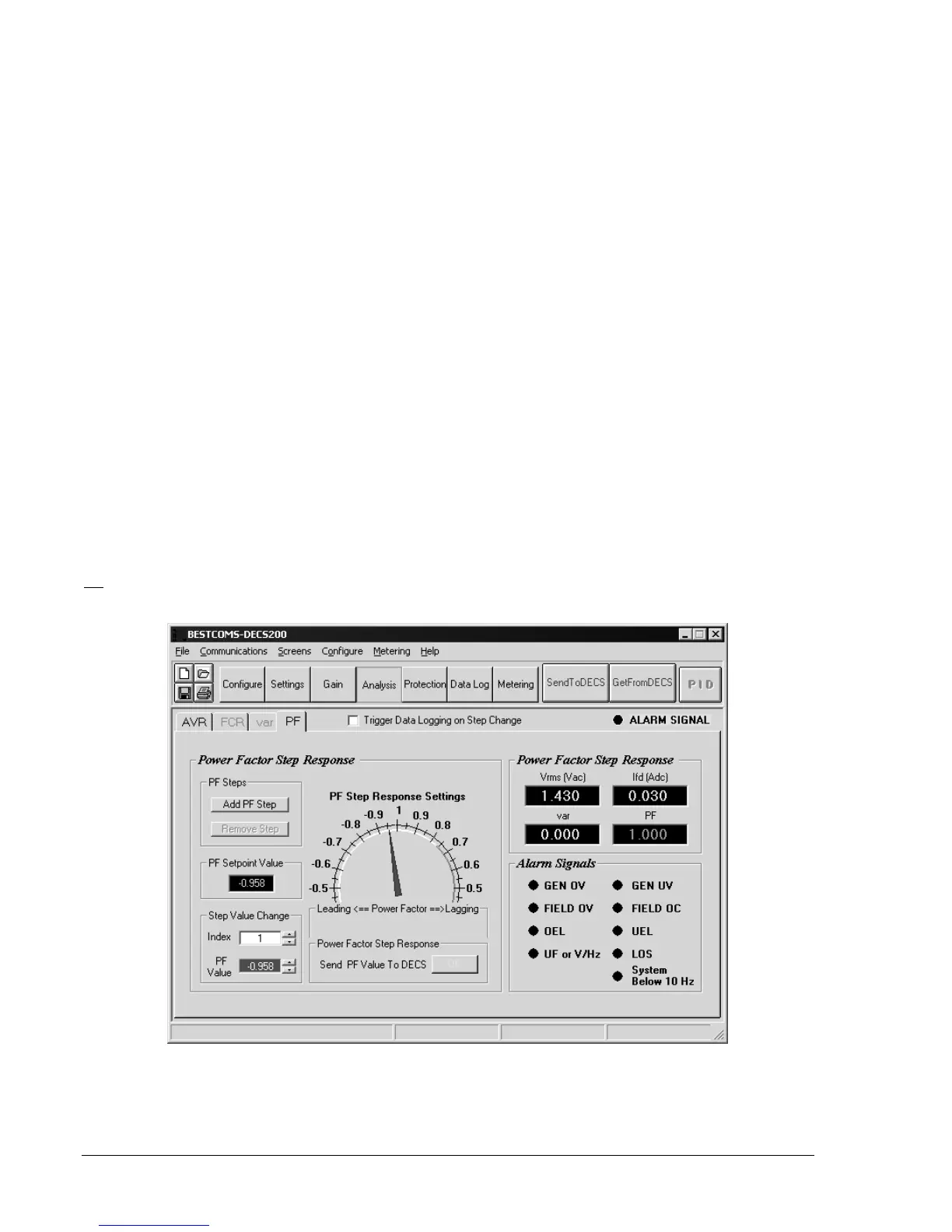
PF
PF tab settings are illustrated in Figure 5-24 and described in the following paragraphs.
Figure 5-24. Analysis Screen, PF Tab
Power Factor Step Response, Add PF Step.
Adds a power factor setpoint index. Up to three setpoint
indexes can be created. The addition of indexes is discussed in the paragraphs describing the Step Value
Change settings.