FUNCTIONAL TESTS Chapter 4
4 - 13
6. (*D*) Set the CAS4004801 fixture onto the barrel clamp cradle and repeat steps 3 and
4. The inches number should be between 0.281 to 0.301 inches (0.281 < inches <
0.301).
7. Open the barrel clamp and remove the fixture.
8. (*D*) Set the CAS4005801 fixture onto the barrel clamp cradle and repeat steps 3 and
4. The inches number should be between -0.024 to +0.026 inches (-0.024 < inches <
+0.026).
NOTE
If the inches number is incorrect, the barrel clamp must be replaced.
9. Open the barrel clamp and remove the fixture.
10. (*D*) Set the CAS4006801 fixture onto the barrel clamp cradle and repeat steps 3 and
4. The inches number should be between 0.989 to 1.041 inches (0.989 < inches <
1.041).
NOTE
If the inches number is incorrect, the barrel clamp must be replaced.
11. Open the barrel clamp and remove the fixture.
12. Press CONFIRM and verify that the pump displays PRESSENS.
4.2.11.7 Pressure Sensor Check: (*D*)
1. Lay the pump down so that the front of the pump faces upward, position the plunger
driver near the top of the pump, and enable the pump’s motor by capturing a coin in
the plunger driver.
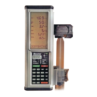
2. (*D*) As soon as the pressure sensor force value appears on the display, view the
display for 10 seconds and verify that this value remains at 0.0 ± 0.15 (-0.15 ≤ value ≤
+0.15) throughout this time period.
3. Press CONFIRM. Observe that, from top to bottom, the display indicates as follows:
VB SENSE
4. Press CONFIRM twice to exit the Calibration Review mode. The pump responds by
repeating the power-on self test (POST) and prompts for a selection.
A/D count number
Voltage (number)
 Loading...

