See chapter 8.1.6
2. Remove the rear cover, to access the interior cables.
See chapter 8.1.1
3. Remove the clamps securing the cables and tubes that emerge from the lower part of the arm that you want to
dismantle.
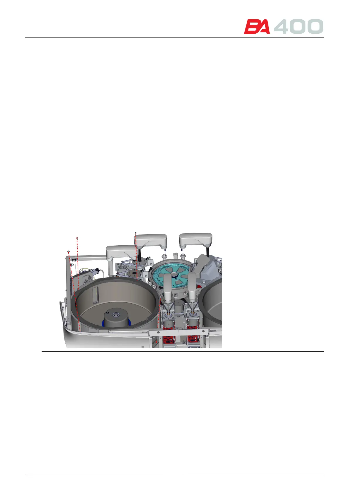
4. Remove the 3 screws (1) securing the arm assembly. Use a screwdriver and lengthener to access the screws.
8.3. Dismantling the reagent rotor
1. Remove the top cover.
See chapter 8.1.6
2. Unplug the 5 fans connected to the CIIM00052 board
3. Unplug the two CAN cables connected to the CIIM00052 board
4. Remove the reagent 2 arm, to leave sucient space for taking out the rotor.
See chapter 8.2
5. Loosen the 5 screws securing the rotor assembly to the base. See Figure 8.7
6. Remove the rotor assembly and follow the steps indicated in Figure 8.8 to take the rotor out of the analyser.
Figure 8.38 Rotor anchoring screws
101