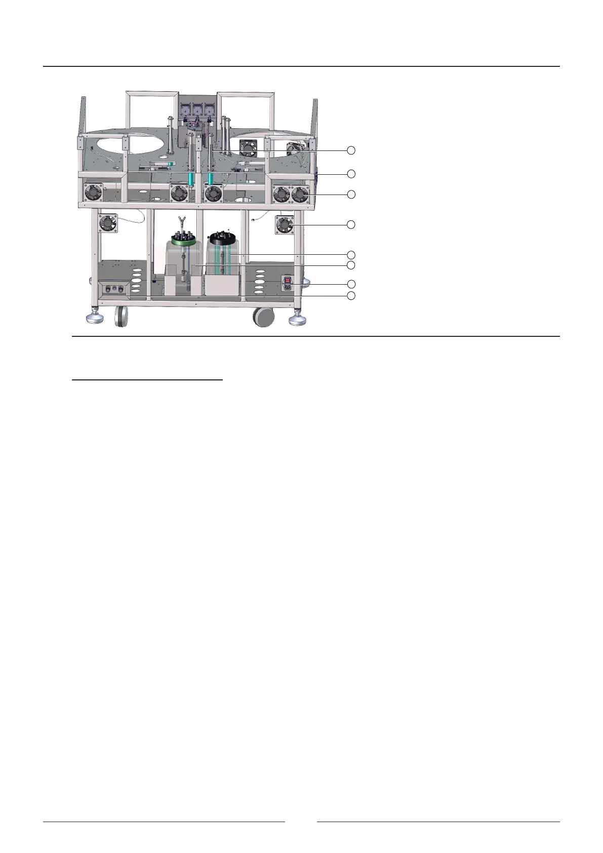
Figure 3.19 Rear view of structure
16
11
14
10
12
17
15
13
References of gures 3.18 and 3.19
1 – Structure
2 – ISE module (optional)
3 – Fridge fans
4 – High contamination waste bottle
5 – Washing solution bottle
6 – ISE module calibration standards kit
7 – Bottle weighing scales
8 – Wheel
9 – Anchoring leg
10 – Wash station for tips
11 – Lateral switches
12 – General fans
13 – Electronic compartment fans
14 – Distilled water bottle
15 – Low contamination waste bottle
16 – Main switch
17 – External uid connections
3.8. Fluid connections
e entire uidic system is mounted on a board located on the right-hand side of the analyser.
To facilitate the identication and monitoring of the uidic system, the tube colour selection uses the following
criterion:
• Blue: Distilled water tubes
• Red: Waste tubes
• Green: Washing solution tubes
Service Manual
30