38
1. Place each of the pins (1) so that they compress the cable in the connector compartment (2). e pins have a
single position.
2. Insert the pins as far as they will go. e pins must be anchored.
3. Insert through the side of the connector (2) the extra anchoring (3) until it clicks into place.
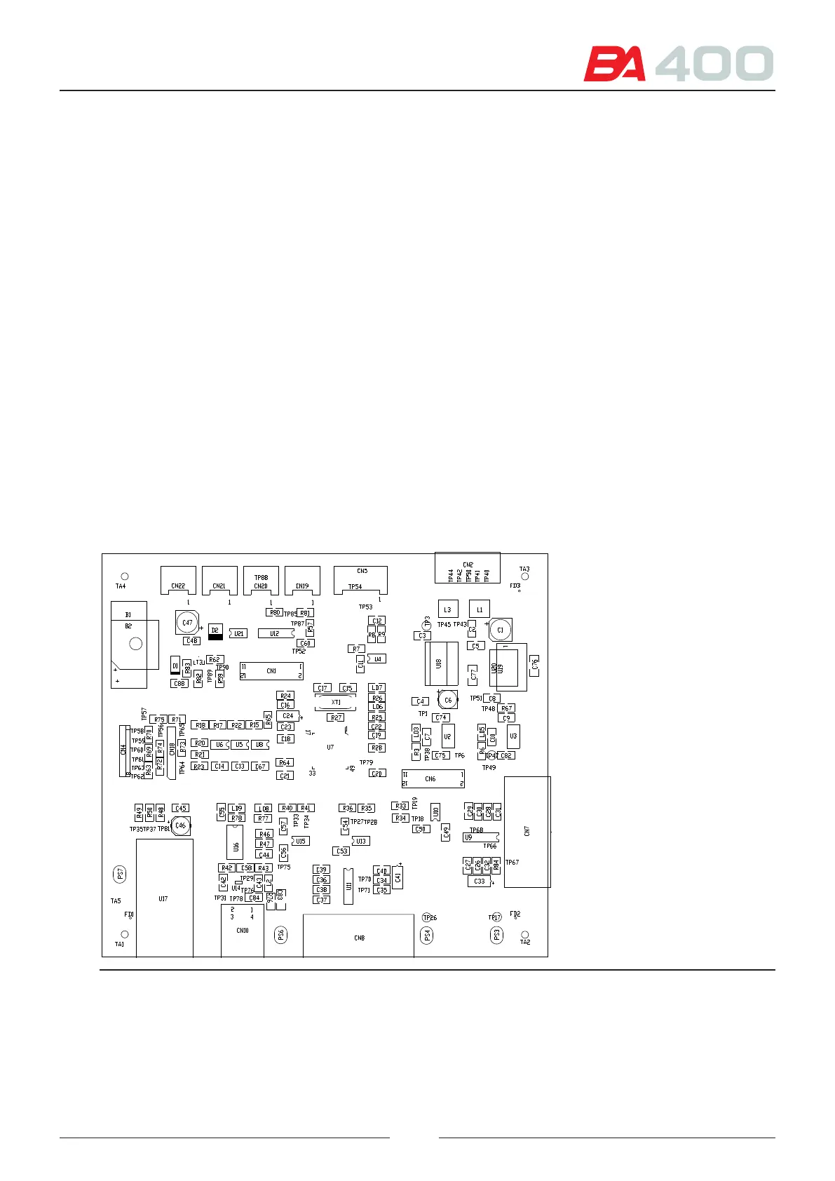
4.2. Main board (CPU) - CIIM00046
is is the main board in which the tasks are distributed (in terms of the rmware) to each of the subassembly boards.
is board also controls the following devices:
• e computer communications through RS-232 and USB
• e analyser status lamp
• e analyser main cover sensor.
• e general fans of the analyser. ese fans have two wires.
• Control in sending the commands for controlling the ISE module and receiving the results thereof.
e electronic control system for the RS-232 for communications and for the ISE module is electrically isolated
from the main electronic system. To supply it with power, use a special insulated regulator (U20 and U3).
USB supplied by the computer and insulated from the equipment electronic system.
Figure 4.6 CPU board silk printing