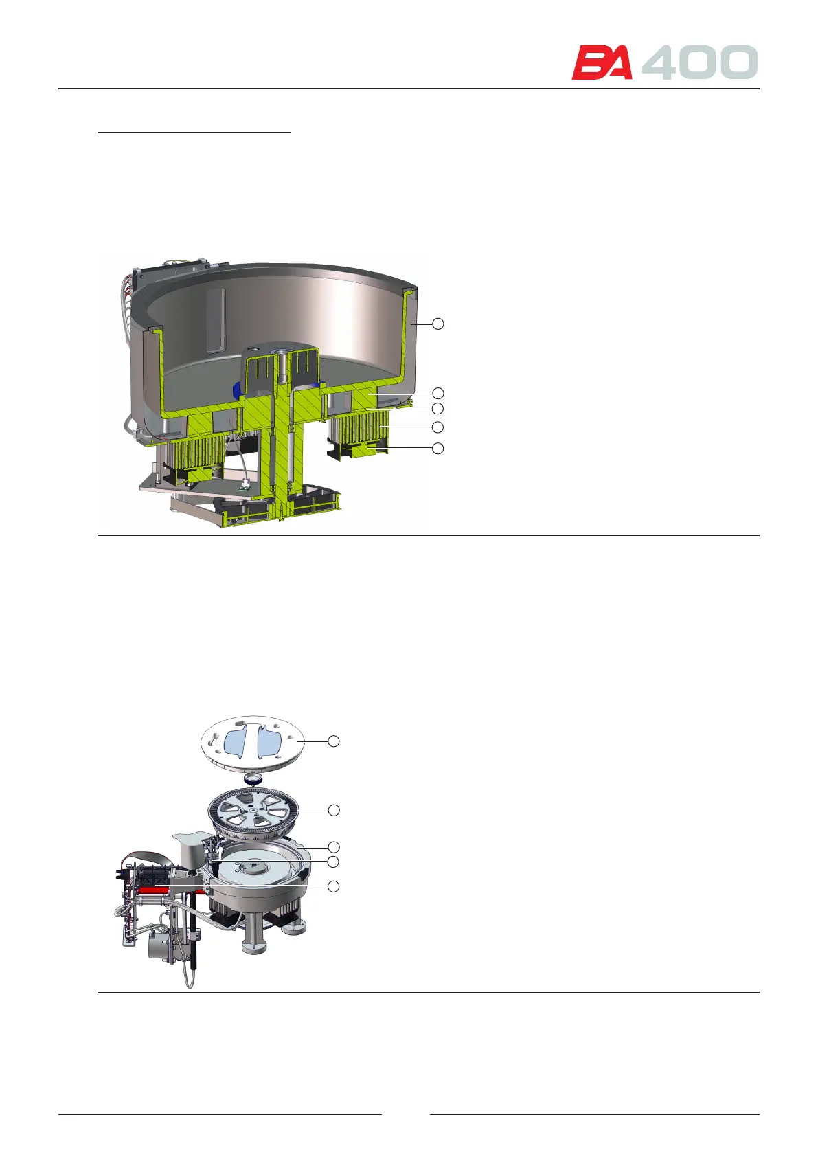
7 – Rotor ball-shaped anchorages
8 – Insulator
9 – Peltier splitter
10 – Peltier
11 – Radiator
12 – Fan
References of gures 3.4 and 3.5:
1 – Reaction rotor cover
2 – 60mL and 20mL reagent bottles
3 – Reagent rotor
4 – Rotor assembly
5 – Rotor anchoring button
6 – Rotor positioning device
8
9
10
11
12
Figure 3.5 Reagent rotor cut-o
3.3. Reaction rotor
e reaction rotor is the place where the sample is mixed with the reagent. e rotor (2) has 120 PMMA wells. e
rotor is installed in a heating canal (3) thermostatted at 37 C. e entire assembly is protected by a cover
(1), to maintain the temperature inside it and prevent light from entering. e system functions continuously and
for this purpose, it has a wash station (4) which empties and washes the rotor wells in 10 cycles. During each cycle,
the analyser reads 68 wells with the optical system (5) that is built into the assembly.
Figure 3.6 Reaction rotor assembly
1
2
3
4
5
21