6. Check in the analyser that the uids enter and leave, depending on the electro valves and pumps that are activated.
7. On exiting the test, all the electro valves and pumps that are active will be deactivated.
8. In circuits in which a pump and an electro valve are next to each other, when the pump is activated the electro
valve will always be activated and when the electro valve is deactivated, the pump will be deactivated.
6.5.5. Adjusting the thermostatting systems
Screen for adjusting the thermostatting of the reaction rotor, the reagent tip assembly and for thermostatting the
wash station.
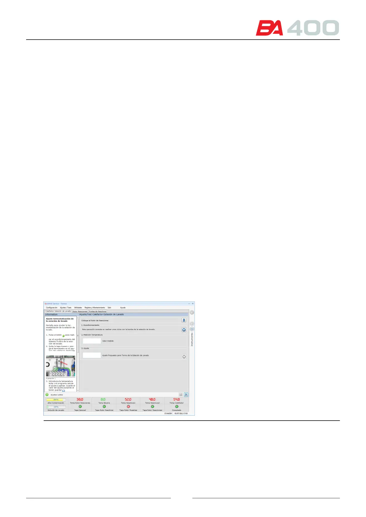
6.5.5.1. Wash station thermostatting adjustment
e distilled water or washing solution dispensed by the wash station are thermostatted beforehand, to prevent
interference with the rotor temperature. e thermostatting adjustment is made in this screen.
See Figure 6.19
Follow the steps to execute the adjustment process:
1. Press the adjustment button of section 1 to execute a uidic conditioning of the system.
2. Remove the rear cover and place the thermometer sensor in the heater measuring point
See Figure 6.20
3. Enter the value of the temperature measured with the thermometer in the box of section 2.
4. Press the adjustment button of section 3 to change the regulation system password if the value measured is out
of the ranges.
Consult chapter AIII to see the ranges accepted in making the wash station heater adjustment.
5. Save the adjustment value.
Figure 6.21 Wash station thermostatting adjustment screen
83