References of gures 3.16 and 3.17
1 – Manifold with electro valves
2 – Board with led lamp
3 – Pressure sensor
4 – Sample pump
5 – Reagent 1 pump
6 – Reagent 2 pump
7 – Output connection tting
8 – 3 mm sample piston
9 – 8 mm reagent piston
10 – Retaining element
11 – Piston support
12 – Pump spindle
13 – Pump motor
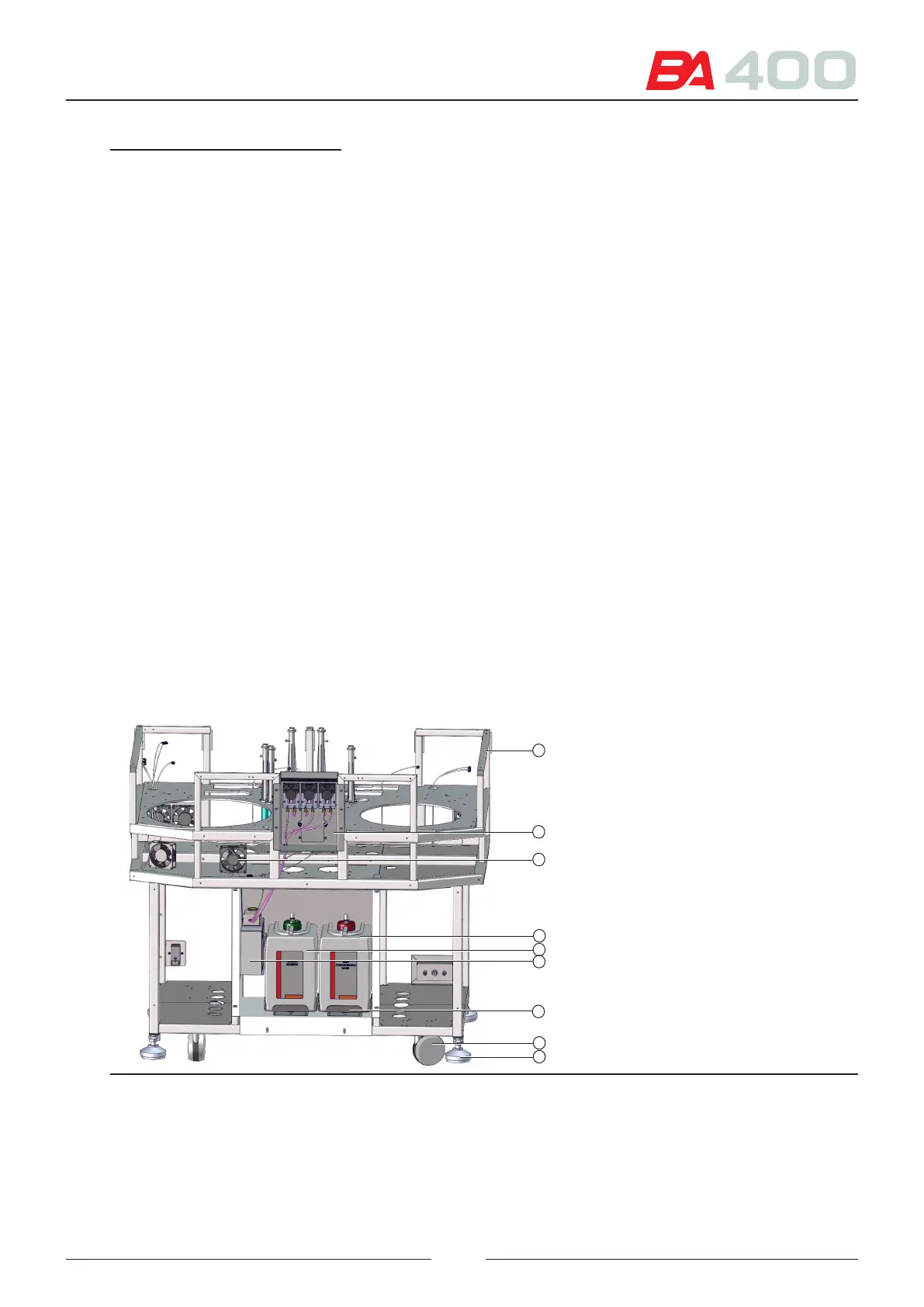
3.7. Structure
Each of the analyser's subassemblies is attached to the structure (1). e sample rotor, reagent rotor, reaction rotor,
sample arm, reagent arm and stirring arm subsassemblies are attached at the top. e pump and uidic subassemblies
are attached at the bottonm right-hand side. e electronics and power supplies are located on the top left-hand side.
e ISE module (2) is located in the centre, at the top, and the ISE module reagent kit (6) is located in the bottom
central part. See Figure 3.18.
e washing solution bottles (5) and high contamination waste bottles (4) are located in the bottom central part.
e volume in the bottles is determining by weighing. Below each bottle is a weighing scale (7).
e general fans (12), (13) are fastened directly to the structure. e fan (3) is attached to the front panel.
e wash stations for each tip and stirrer (10) are attached directly to the structure. e evacuation tubes are con-
nected directly to the low contamination waste bottle. e distilled water bottles (14) and low contamination waste
bottles (15) can be accessed from the rear bottom part. Double buoy sensors are used to detect the maximum and
minimum levels of each container.
e main switch is located at the bottom right-hand side (16), and the partial switches at the side (11).
e external uidic connections are located at the bottom left-hand side (17).
Figure 3.18 Front view of structure
9
4
6
1
3
5
2
8
7
29