Service Manual
33
4. Electronic elements
e electronics controlling the analyser are laid out in 14 independent boards. Each board controls an analyser sub-
assembly. e method for transmitting the information between the boards is through a CAN communication bus.
ere are 2 more boards which are used to make the CAN bus interconnection.
Some boards perform the same function and are repeated, for instance the boards that control the arms. To enable the
information to be communicated through the bus and reach the correct board, the board must have a single identier
inside the analyser. For this reason each board has a series of switches so that the board identier can be selected.
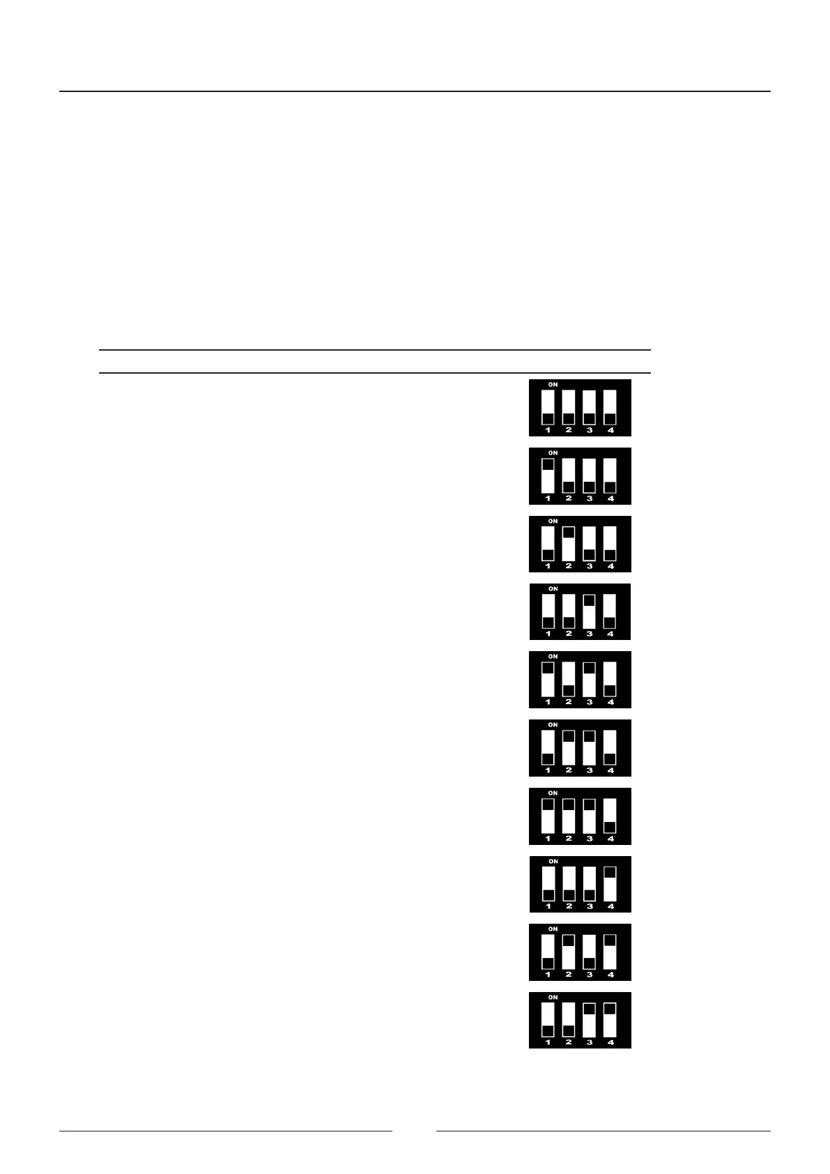
e code assigned to each board is indicated below:
Type of board Description of board Identication code Selector position
Arm boards Sample 1 arm
BM1
0000
Reagent 1 arm
BR1
1000
Reagent 2 arm
BR2
0100
Stirrer 1 arm
AG1
0010
Stirrer 2 arm
AG2
1010
Detection boards Sample 1 detection
DM1
0110
Reagent 1 detection
DR1
1110
Reagent 2 detection
DR2
0001
Rotor boards Sample 1 rotor
RM1
0101
Reagent 1 rotor
RR1
0011