34
Type of board Description of board Identication code Selector position
Fluidic system
board
Fluidic system
SF1
1111
Syringe board Syringes
JE1
0100
Each of the above boards has a microprocessor. To rapidly identify the microprocessor status, they have a built-in
state indicator led. e information provided by the ashing of the led is the following:
Status Description
Rapid ashing (burst) Board start-up. After a few seconds, the ashing changes to slow.
Rapid ashing Board in monitor mode.
Slow ashing Board has rmware and is operating correctly.
Very rapid ashing. With
no regular sequence
Firmware update process.
Not ashing Board not supplied with power or damaged.
NOTE
e analyser chassis, and all its metallic parts are only connected to the socket ground wire. is is
the electrical safety wire.
e negative reference or GND of the electrical circuit is isolated from the chassis. To measure the
voltages with a multimeter or an oscillocope, place the instrument reference at the “test points”
marked GND in each board or the CAN connector reference connection.
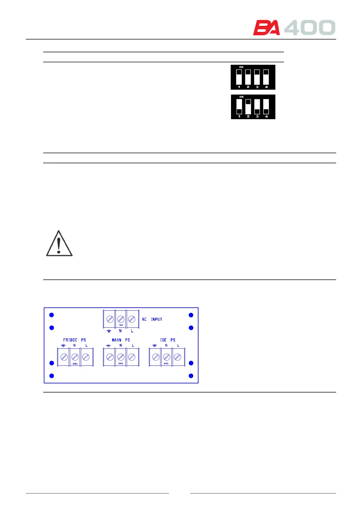
Figure 4.21 Sources and input-AC board - CIIM00056
Figure 4.1 Silkscreen printing of input-AC board