18
19
20
Figure 3.3 Barcode reader adjustment
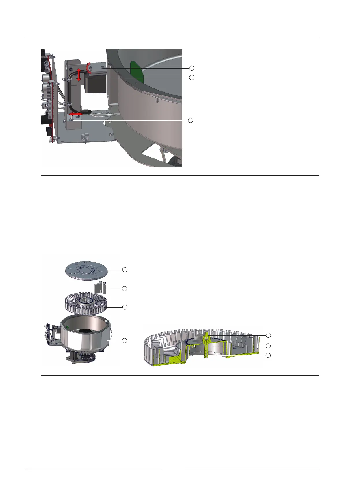
3.2. Reagent rotor
e reagent bottles are placed in the reaction rotor. ere are two types of bottle, one containing 60mL and one
containing 20mL. e rotor (3) has 2 rings. Only 20mL bottles can be placed in the outer ring, and both 20mL
and 60mL bottles can be placed in the inner ring. e assembly has a barcode reader that reads the codes on the
bottles placed in both rings. e whole assembly is refrigerated and has a separate power supply system to maintain
the refrigeration when the appliance is turned o.
1
2
3
4
5
6
7
Figure 3.4 Sample rotor assembly
e rotor transmission system and the barcode reader support and adjustment are exactly the same as those of the
sample rotor.
See chapter 3.1, description of the transmission system and barcode reader support.
e reagent rotor compartment is refrigerated. To maintain the temperature, the vessel is protected by an insulator
(8). e cooling system is performed by 4 peltiers (10) that cool the vessel through the copper splitters (9). e heat
produced by the peltiers is evacuated through the radiators (11) and fans (12).
Service Manual
20