e start-up sensor (12) ensures the initial position of the sample rotor by means of a tab on the pulley.
e vessel exterior is protected by a cover (1). A Hall eect sensor (8) indicates that the cover is on the analyser.
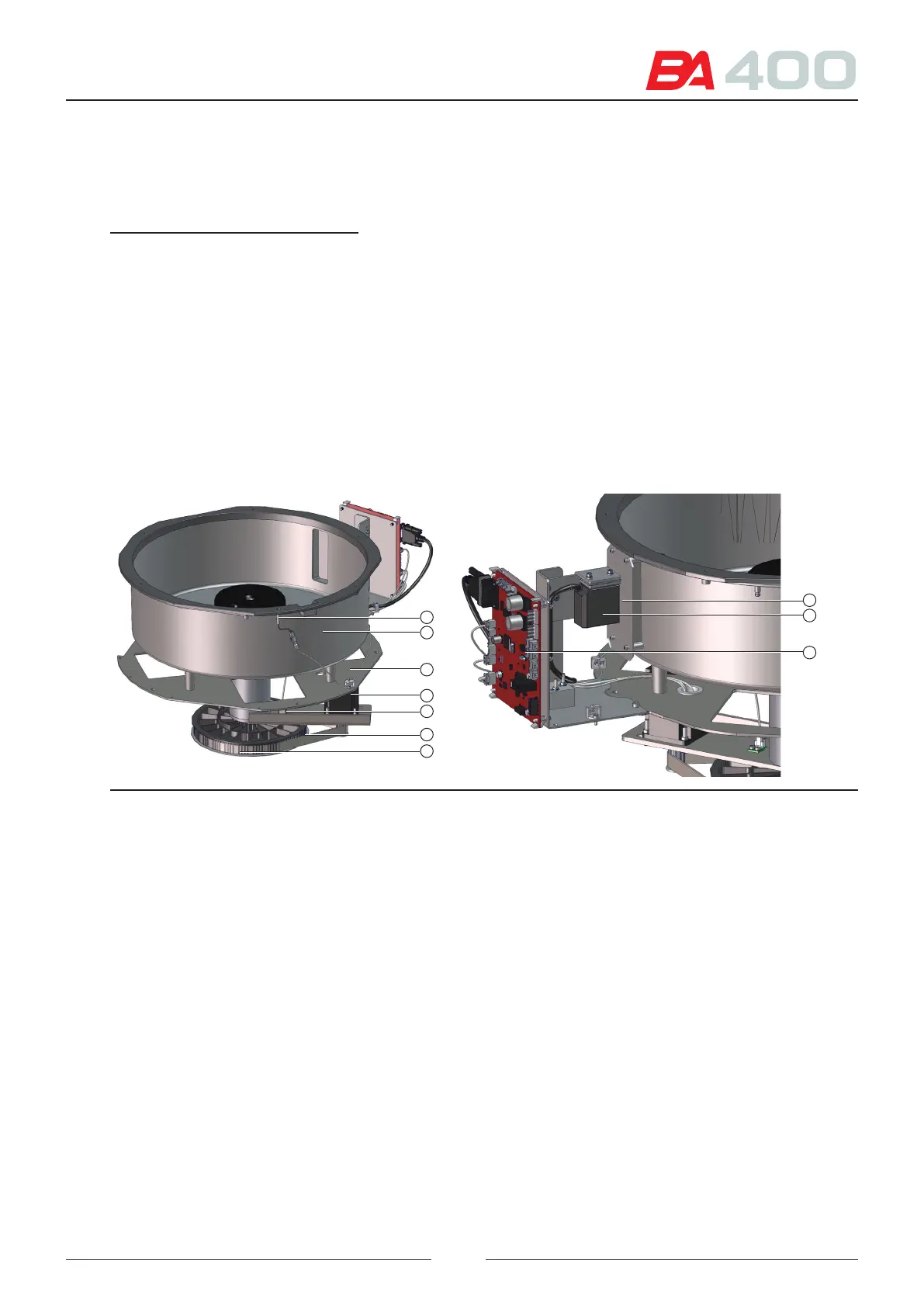
References of gures 3.1, 3.2 and 3.3:
1 – Sample rotor cover
2 – Adapters for tube and sample well
3 – Sample rotor
4 – Rotor assembly
5 – Rotor anchoring button
6 – Rotor positioning device
7 – Rotor ball-shaped anchorages
8 – Cover sensor
9 – Rotor vessel
10 – Rotor assembly support
11 – Rotor circular movement motor
12 – Rotor start-up sensor
13 – Transmission belt
14 – Pulley
15 – Barcode reader protective window
16 – Barcode reader
17 – CIIM00052 electronic board
18 – Set screw for angular orientation of barcode reader
19 – Set screw for adjusting the barcode reader height
20 – Set screw for barcode reader proximity adjustment
15
16
17
8
9
10
11
12
13
14
Figure 3.2 Detail of sample rotor assembly
e barcode reader (16) is secured by a support to the subassembly structure. It is positioned at the correct height
for the light to correctly illuminate the tubes placed in the rotor.
ere is a protective window to isolate the reader from the exterior.
e barcode reader position can be adjusted using mechanical means.
See chapter 6 for applying the service programme and reader adjustment, and Figure 3.3.
• To adjust the angular orientation, loosen the screws (18) and move the reader with your hand until you obtain
a correct reading. Tighten the screws (18).
• To adjust the reader height, loosen the screws (19) and move the reader upward or downward with your hand.
Once the readings are correct, tighten the screws (19).
• To adjust the reader proximity, loosen the screws (20) and move the reader forward or backward with your
hand. Once the readings are correct, tighten the screws (20).
19