Service Manual
49
Test point Function
TP41 Motor driver step voltage
TP51 Rotor temperature
LEDs Function (on condition)
LD1 3.3 V activation
LD2 CPU start-up
LD3 Wash station rest phase detection
LD4 Rotor start-up detection
LD5 Wash station start-up detection
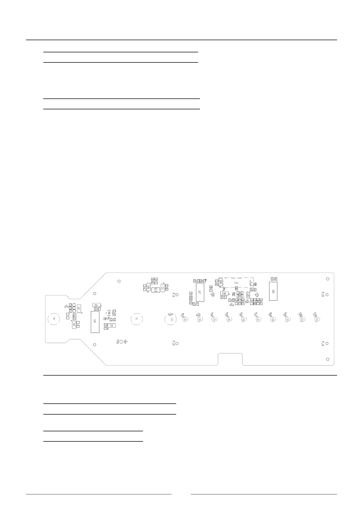
4.6. Photometric readings board - CIIM00051
is board is located below the optical bench in the reaction rotor assembly. e board has the leds for each wave-
length and the two photosensors directly welded to it.
is board controls the switching on and o of each led. e leds are controlled through a power source (U2, U8,
U9 and T13) and the led on selection is done through a decoder (U11).
e readings are made through two photodiodes (main and reference photodiodes) which are read by a double
integrating ramp converter (U1, U4, U5 and U6).
All the control signals are sent to the photometric control board (CIIM00050) through an I2C channel (U7)
Figure 4.14 Photometric control board silk printing
Connector Function
CN1 Photometric board connection
Test point Function
TP3 LED voltage
TP4 LED voltage
TP6 Decoder 1