46
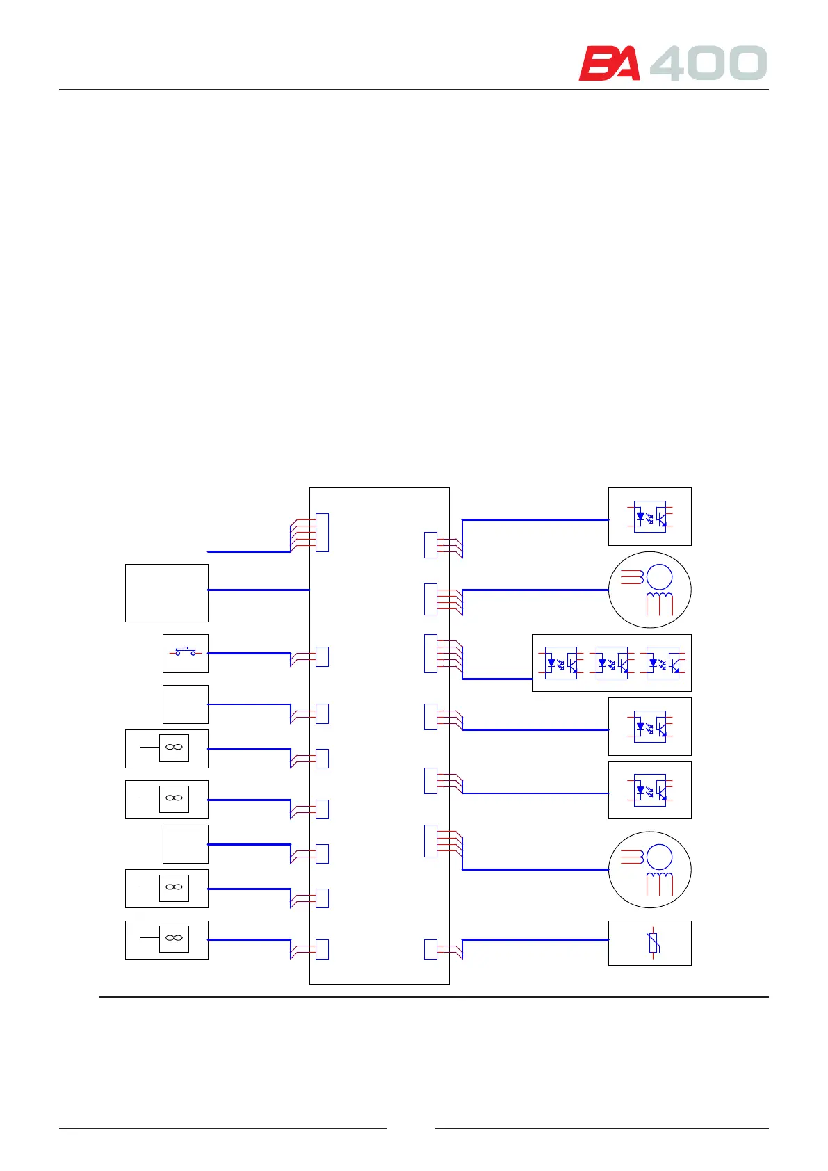
4.5. Photometric control board- CIIM00050
Board located in the reading rotor. It contains a micro controller (U5) which controls the following elements:
• Reaction rotor cover detection (U7)
• Wash station motor (U14)
• Wash station start-up detection (U10)
• Wash station collision detection (U10)
• Photometric board connection
• Reaction rotor motor (U12)
• Reaction rotor start-up detection (U10)
• Reaction rotor encoder detection (13)
• Peltier control in thermostatting the reaction rotor (U18)
• Fan control for cooling the peltiers (U17). ere are 3 fans with 3 wires.
• Reaction rotor thermostatting temperature sensor control (U15 and U16)
CIIM00050
CAN BUS
ROTOR
DETECTOR
ROTOR
MOTOR
GLF1
PLMA00321
PLMA00307
PLMA00308
PLMA00306
WASHING
STATION
HOME
WASHING
STATION
MOTOR
PLMA00310
TEMPERATURE
SENSOR
FAN
PLMA00309
FAN
PLMA00311
PELTIER
PLMA00314
ROTOR
COVER
DETECTOR
PLMA00320
CIIM00051
PLMA00316
CN1
CN5
PLMA00318
WASHING
STATION
COLLITION
DETECTOR
FAN
PLMA00312
FAN
PLMA00313
PELTIER
PLMA00315
ENCODER
ROTOR
CAN BUS
PHOTOMETRYPHOTOMETRY
ROTOR COVER
FAN
FAN
HOME ROTOR
ROTOR
WS COLLISION
HOME WASHING ST.
WASHING STATION
THERMISTOR
ROTOR COVER
FAN
FAN
FAN
FAN
THERMISTOR
WASHING
STATION
HOME
WASHING ST.
WS COLISION
ENCODER
ROTOR
HOME ROTOR
PLMA00319
ENCODER
CN13CN13
1
2
CN17CN17
1
2
CN1CN1
1
2
3
4
5
1 6
2
5
4
CN3CN3
1
2
1
2
3
4
5
6
+tº+tº
12
CN8
CON3
CN8
CON3
1
2
3
CN12CN12
1
2
1
2
3
4
5
6
CN14CN14
1
2
1 6
2
5
4
CN16CN16
1
2
CN6CN6
1
2
3
4
1 6
2
5
4
CN9CN9
1
2
3
4
1 2
CN7CN7
1
2
3
4
5
CN15CN15
1
2
1 6
2
5
4
CN4
CON3
CN4
CON3
1
2
3
CN10
CON3
CN10
CON3
1
2
3
CN11CN11
1
2
1 6
2
5
4
1 6
2
5
4
Figure 4.12 Photometric control board connections