3. Mechanical elements
In mechanical terms, the analyser has a tubular structure to which the dierent subassemblies and housing elements
are attached.
e analyser has the following subassemblies:
• Sample rotor
• Reagent rotor
• Reaction rotor
• Pipetting arms
• Stirring arms
• Wash station
• Dosing system
• Fluidic system
• ISE module (optional)
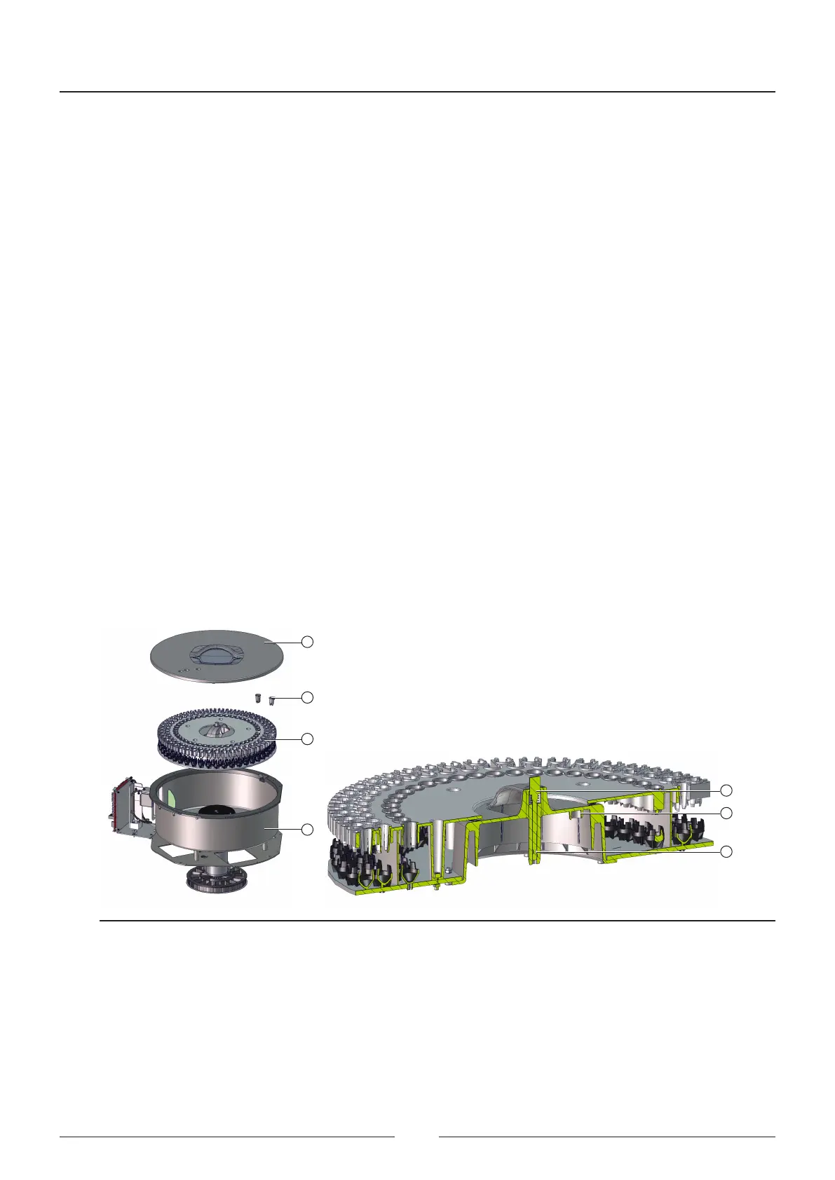
3.1. Sample rotor
e tubes with the patient serum samples and the wells with the calibration standards and controls are placed in the
sample rotor. e rotor (3) has 3 rings. Tubes with larger diameters (16 mm) are placed directly in the holes. Tubes
with smaller diameters or sample wells require the use of adapters (2) to secure them in place.
1
2
3
4
5
6
7
Figure 3.1 Sample rotor assembly
e rotor (3) has a single position once it has been inserted into its compartment (4). For this reason it has a cen-
tring device (6) to guide it. Once inserted, the rotor cannot be removed as it is blocked by a ball-shaped anchoring
device (7). To release the rotor from the base it is necessary to press the button (5).
e rotor vessel (9) is secured to the rotor assembly support (10). e rotor (3) is connected to the rotor centring
device, which in turn is connected to the pulley by a shaft (14). e belt (13) transmits the motor movement (11)
to the whole assembly.
Service Manual
18