Service Manual
35
5
5
4
4
3
3
2
2
1
1
D D
C C
B B
A A
N
E
P
N
E
P
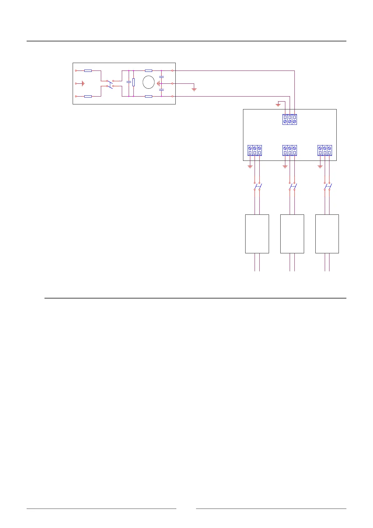
FN 284-10-06
MAIN PS ISEFRIDGE PS
UNIVERSAL INPUT
94V - 264V
600W
AC INPUT
PLMA00258
CIIM00056
FRIDGE PS MAIN PS ISE
FA
FRIDGE
FA
MAIN
FA
ISE
SP-320-24
24V 13A
SP-320-24
24V 13A
RS-35-24
24V 1.5A
FA FRIDGE FA SF1 FA ISE
FA MAIN
FA MAIN
EMC
CN1CN1
1
2
3
CN4CN4
1
2
3
CN3CN3
1
2
3
CN2CN2
1
2
3
Figure 4.2 Power supply input connection diagram.
4.1. Distribution board - CIIM00047
e distribution board is responsible for making the connection for each of the dierent boards. e connections
are made by the CAN bus. e bus cable distributes the power for each board and the CAN signals.
Both distribution boards are identical and each connector bears silk printing indicating the subassemblies to which
they are connected.
Each connector has two silk prints, one of which is used for board A and the other for board B. Distribution board
A is the board located in the top position, and distribution board B is located in the bottom position.