36
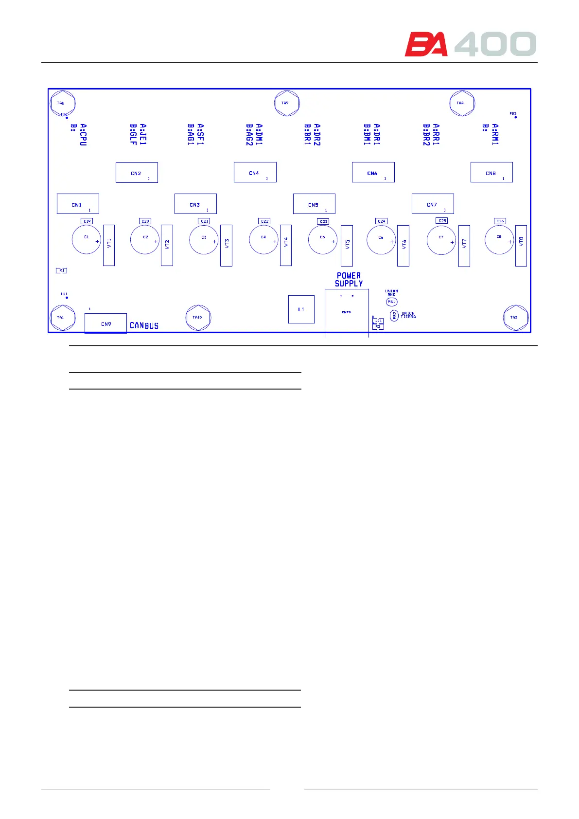
Figure 4.3 Distribution board silk printing
Connector Function
CN1 A
CN1 B
Connection to the CPU board
CN2 A
CN2 B
Connection to the JE1 board
Connection to the GLF board
CN3 A
CN3 B
Connection to the SF1 board
Connection to the AG1 board
CN4 A
CN4 B
Connection to the DM1 board
Connection to the AG2 board
CN5 A
CN5 B
Connection to the DR2 board
Connection to the BR1 board
CN6 A
CN6 B
Connection to the DR1 board
Connection to the BM1 board
CN7 A
CN7 B
Connection to the RR1 board
Connection to the BR2 board
CN8 A
CN8 B
Connection to the RM1 board
CN9 Interconnection of distribution
boards, only for the CAN
CN20 Connection to the power source
LEDs Function (on condition)
LD1 Voltage of 24 V
e CAN connectors are supplied with an anchorage system to ensure their connection.