Service Manual
37
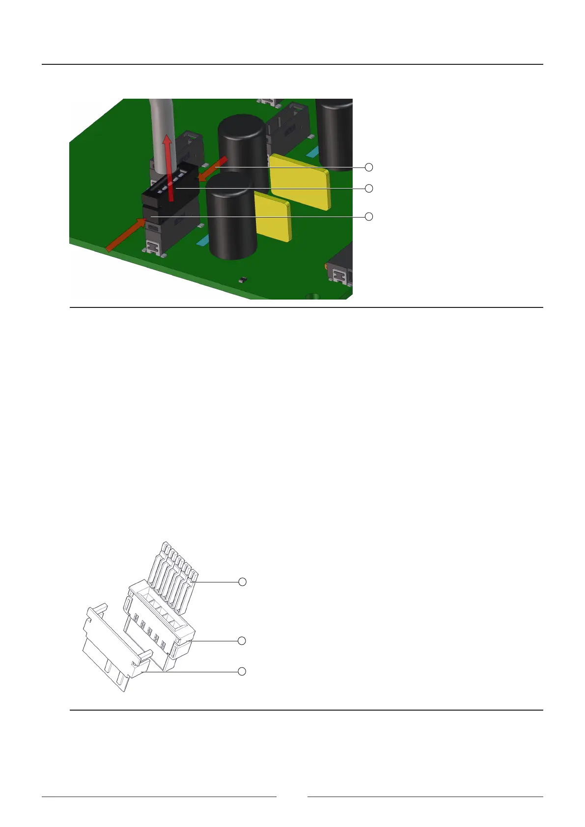
If it should be necessary to remove a CAN cable, take the following steps (see Figure 4.4):
2
1
1
Figure 4.4 Disconnecting a CAN connector
1. Press the sides of the connector rmly (1). ere are tabs on each side for insertion into the female connector.
2. Pull the connector and cable outward (2).
3. Do not pull the cable directly.
4. If you cannot remove the cable, use a pair of at tip pliers that are wide enough to push the tabs.
All the CAN cables have three labels placed at their ends.
• One label indicates to which board it is connected and the board identier, and is used to distinguish the cables
by their lengths, given that in terms of their construction, all the cables are identical.
• e other two labels are at both ends of the cable, one is yellow and the other is white. e end with the yellow
marks is the one that must be connected to the distribution board.
2
1
3
Figure 4.5 Itemised description of the CAN connector
Figure 4.5 shows a CAN connector with the pins (1), connector (2) and extra anchoring (3).
Steps for mounting a CAN connector: