References of gures 3.13 and 3.14
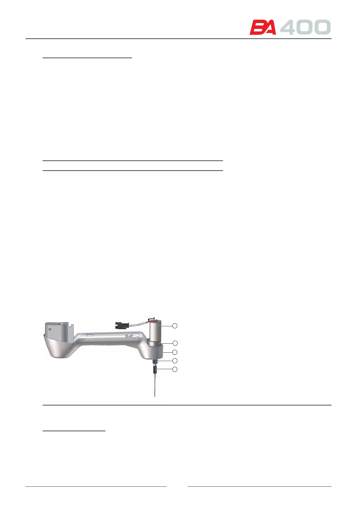
1 – Housing
2 – CIIM00049 board
3 – Angular movement transmission belt
4 – Angular movement motor
5 – Elevation movement initiation photosensor
6 – Aspiration and dispensation tip
7 – CIIM00048 board
8 – Elevation movement transmission belt
9 – Elevation movement guide tube
10 – Elevation movement motor
11 – Elevation movement transmission pulley
12 – Tip thermostatting system cable
13 – Tip temperature sensors cable
14 – Tip detection system cable
15 – Collision detection photodiode
16 – Tip collision detection system
17 – Angular movement initiation photodiode
e only dierence between the reagent and sample arms is the tip (6).
Characteristics of the reagent tip and the sample tip:
Reagent tip Sample tip
Inner diameter at the end 0.8 mm 0.4 mm
Maximum volume contained
inside
500 mL 40 mL
ermostatted Yes No
Temperature sensor Yes No
Fluid detection Yes Yes
e tip control board CIIM00049 (2) is the same for the reagent arm and the sample arm.
3.5. Stirring arm
e elevation and rotation movement assembly part is the same as the pipetting arm assembly.
See section 3.4 for a detail of the assembly.
e stirrer is formed by a at blade(5). e blade is inserted into the continuous current motor shaft (1) and pressed
by a clamping nut (4). e motor (1) is attached to the head piece support (3) by an adapter (2).
Figure 3.15 Stirrer arm head
4
2
5
3
1
References of gure 3.15
1 – Continuous current motor
2 – Adapter
3 – Head support
4 – Clamping nut
5 – Stirrer blade
27