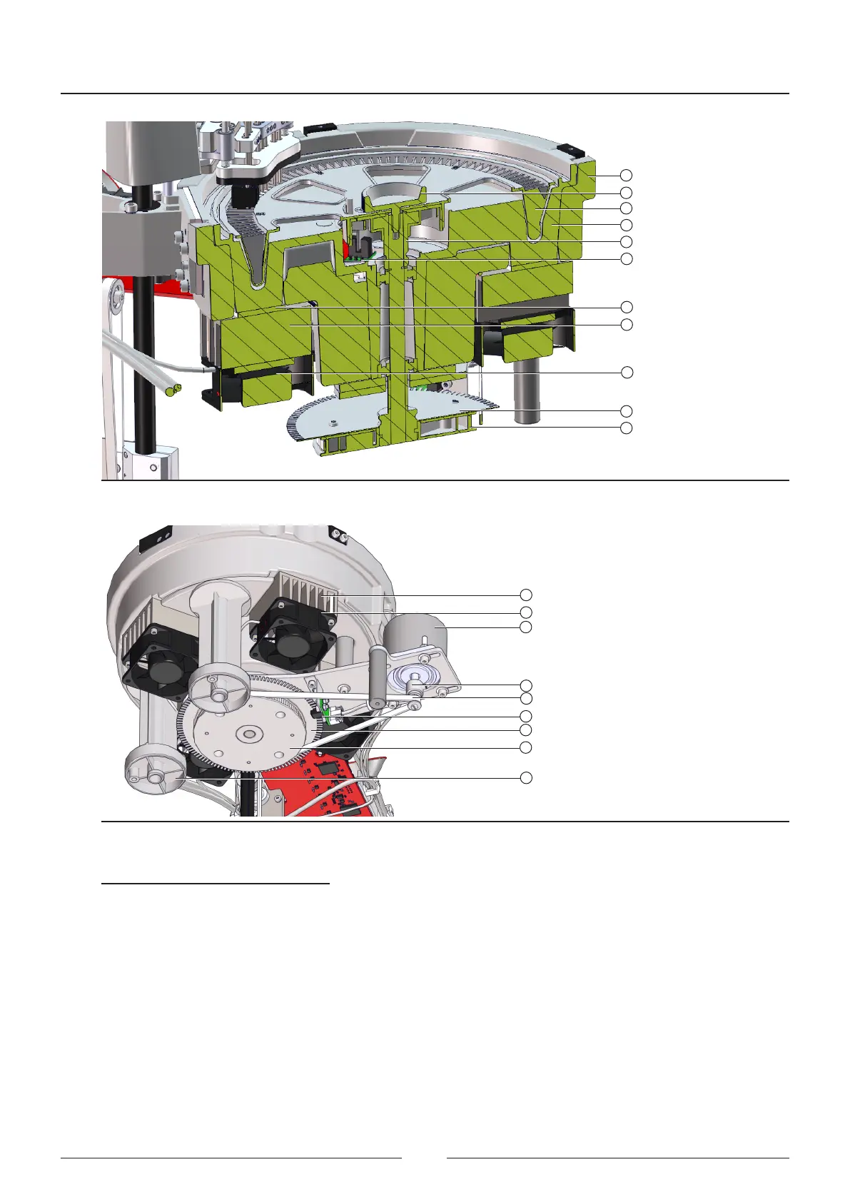
Figure 3.7 Reaction rotor cut-o
6
7
2
4
8
10
11
12
13
14
9
Figure 3.8 Reaction rotor transmission assembly
11
12
15
16
17
13
14
19
18
11 – Radiator
12 – Fan
13 – Reading encoder
14 – Transmission wheel
15 – Rotor motor operation
16 – Motor pinion
17 – Transmission belt
18 – Encoder photosensor
19 – Rotor assembly support column
References of gures 3.6, 3.7 and 3.8:
1 – Reaction rotor cover
2 – Reaction rotor
3 – Heating canal
4 – Wash station
5 – Optical system
6 – Heating canal insulator
7 – Rotor anchoring bolt
8 – Rotor centring device
9 – Rotor start-up sensor
10 – Peltier
Service Manual
22