Service Manual
39
CAN BUS
STATUS LED
BICOLOUR
FAN
CPU
PLMA00286
DETECTOR COVER
CN8
CN7
CN10
CPU F. FAN1
PLMA00285
CIIM00046
COVER SENSOR
LED STATUSCAN BUS
LED STATUS
RS-232
ISE
USB
F.FAN1
COVER SENSOR
CN2CN2
1
2
3
4
5
GREEN
ORANGE
GREEN
ORANGE
1
2
3
USBUSB
1
2
3
4
5
1 6
2
5
4
CN20CN20
1
2
CN1
CON3
CN1
CON3
1
2
3
RS-232 -ISE MODULERS-232 -ISE MODULE
5
9
4
8
3
7
2
6
1
CN21CN21
1
2
CN3CN3
1
2
RS-232RS-232
5
9
4
8
3
7
2
6
1
CN21CN21
1
2
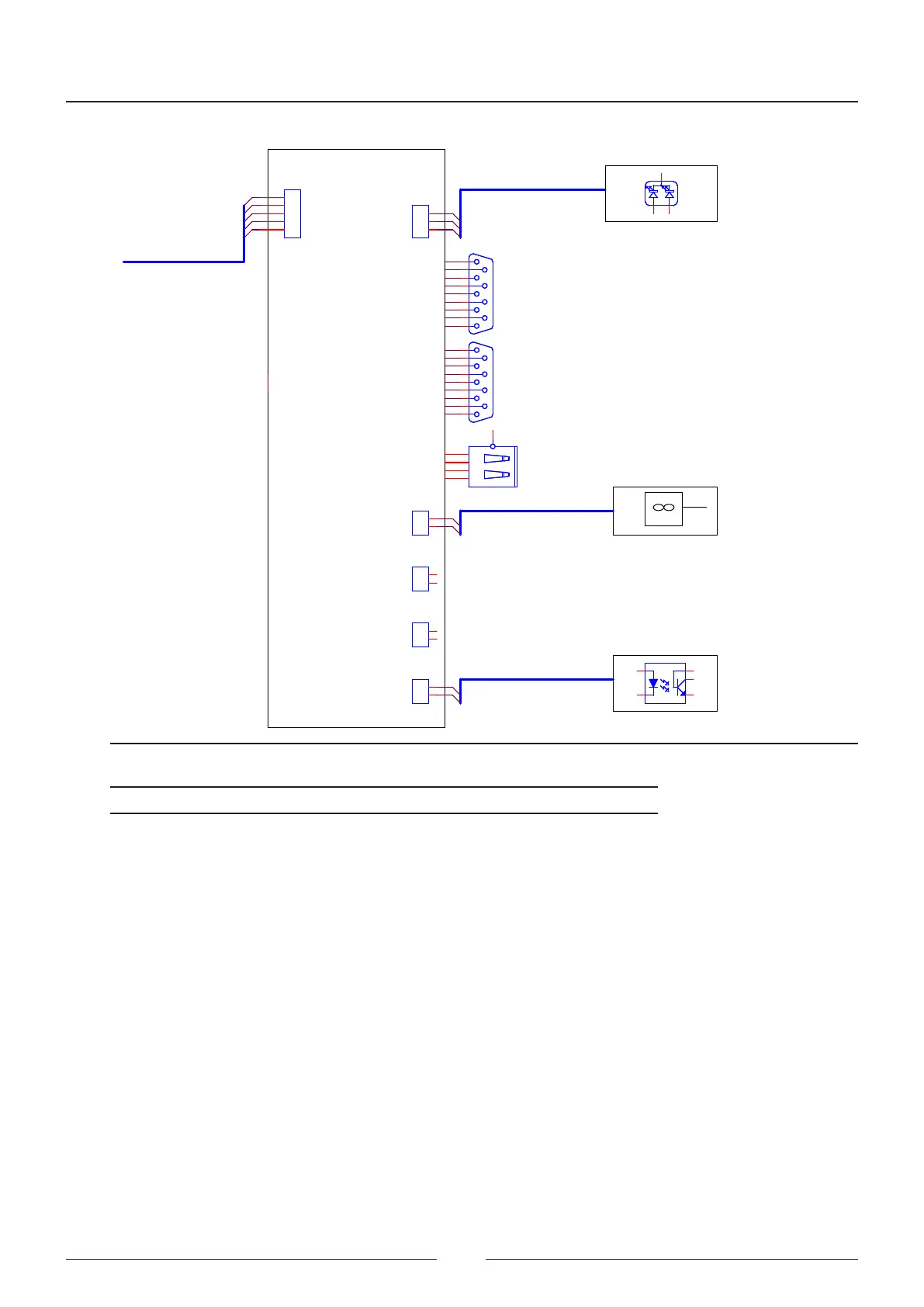
Figure 4.7 CPU board connections
Connector Function Pin
CN2 CAN bus connection Pin 1: 24V
Pin 2: GND
Pin 3: NC
Pin 4: CAN_H
Pin 5: CAN_L
CN1 Led status lamp (3-coloured) Pin 1: Activation of LED1
Pin 2: GND
Pin 3: Activation of LED2
CN7 ISE module serial channel Pin 2: Transmission
Pin 3: Reception
Pin 5: GND
CN8 Analyser serial channel Pin 2: Transmission
Pin 3: Reception
Pin 5: GND
CN10 USB connection Pin 1: 5 V
Pin 2: USB+
Pin 3: USB-
Pin 4: GND