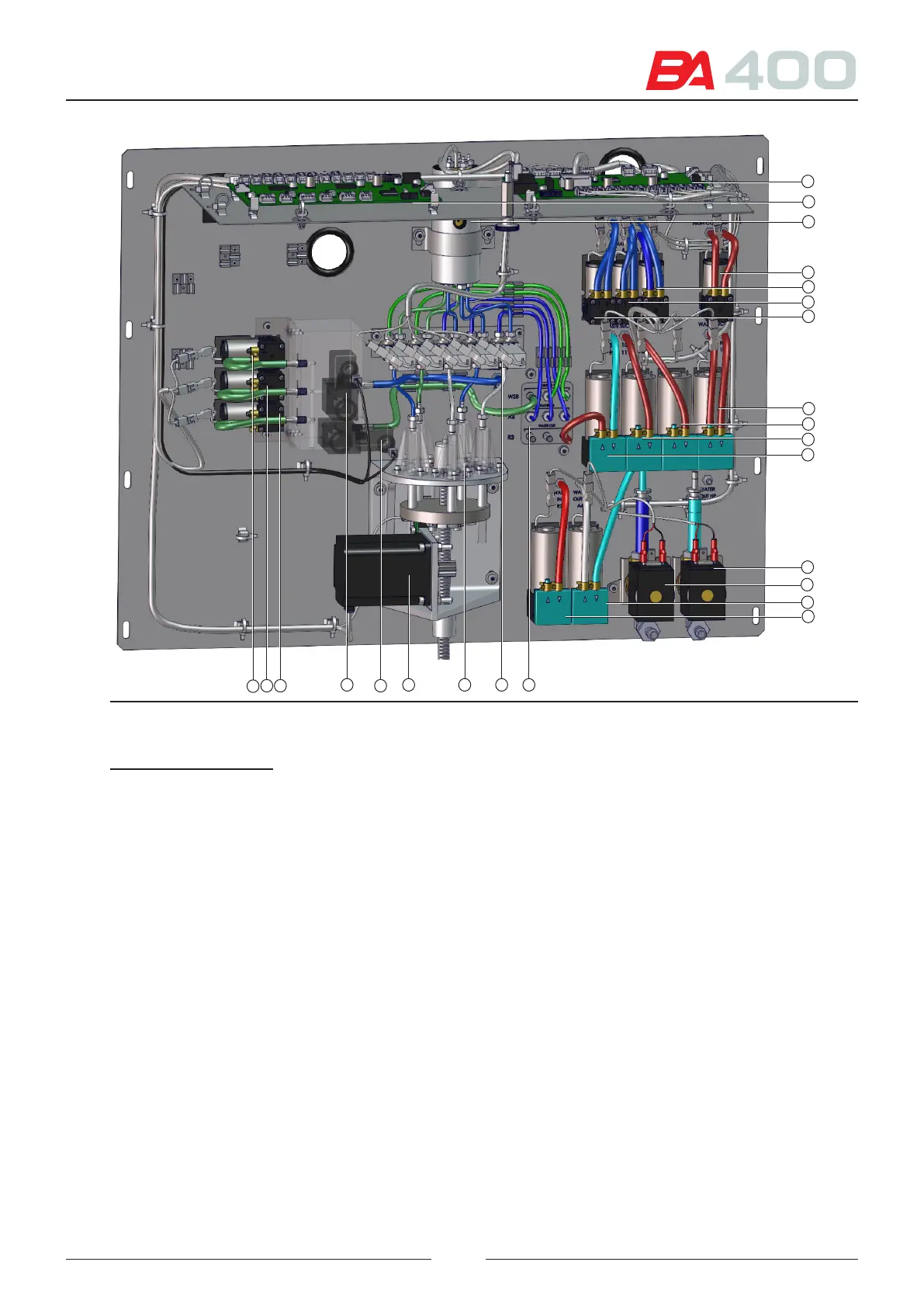
Figure 3.20 Fluidic system assembly
12
3
8
1
4
13
9
5
2
14
15
10
11
6
7
16171819
20
21
2223
24
References of gure 3.20
1 – SF1 board - uidic system control
2 – JE1 board - syringe control
3 – Wash station tube heater
4 – SF1-B10 pump
5 – SF1-B3 pump
6 – SF1-B2 pump
7 – SF1-B1 pump
8 – SF1-B9 pump
9 – SF1-B8 pump
10 – SF1-B7 pump
11 – SF1-B6 pump
12 – SF1-EV1 electro valve
13 – SF1-EV2 electro valve
14 – SF1-B4 pump
15 – SF1-B5 pump
16 – Manifold
17 – SF1-GE1 electro valve
18 – Wash station pump
19 – Wash station motor
20 – JE1-EV4 electro valve
21 – JE1-EV5 electro valve
22 – JE1-B1 pump
23 – JE1-B2 pump
24 – JE1-B3 pump
e water can enter the analyser in two ways:
• rough a pressurised water system
• rough an external tank with a large capacity
e user programme will select the water entry method. In the rst case, the programme will activate the electro
valve (12) and ll the intermediate distilled water tank.
In the second case the programme will activate the electro valve (13) and the pump (14), to suction water from the
external tank.
31