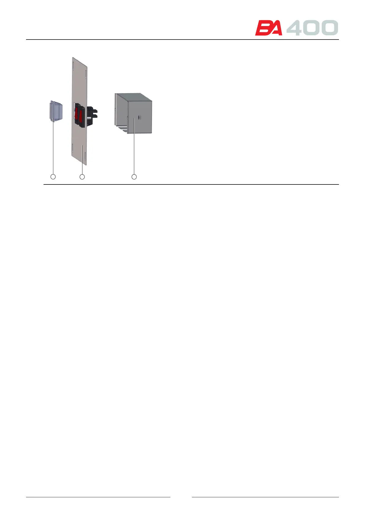
Figure 8.43 Dismantling the switch assembly
1
32
9. Lower the cabling through the analyser column (4). See Figure 8.13.
10. Install the power supply (5) as shown in the previous gure.
11. Connect one of the cable ends to the power supply.
12. Connect the other end to the AC distribution board (6).
13. Connect the module power cables to the power supply output. ese cables are already installed in the analyser.
14. Insert the module in its compartment. See Figure 8.15. Use the same screws that secure the cover to screw the
module in place.
15. Place the pincer (9) of the calibration standard kit in the compartment located next to the internall bottles.
See Figure 8.16
16. Pass the tubes through the two openings (10) and (11) until they reach the module.
17. Consult the user manual chapter on installing the ISE module to see how to connect the dierent tubes and
install the electrodes and standard kit.
18. Replace all the covers and housings.
19. Install the cable gland in the sample dispensing opening in the top cover
105