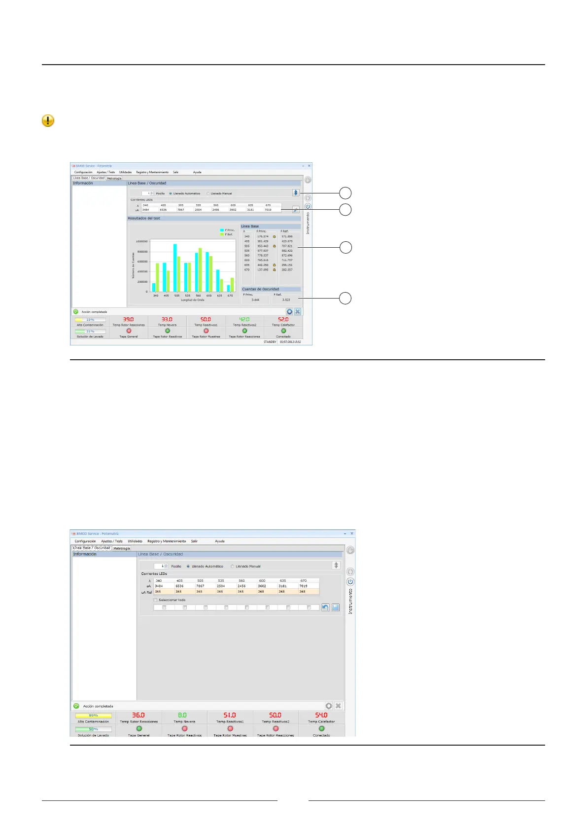
5. A bar chart is shown in position (3) of the screen with the numerical values of the results for the number of
counts obtained for the main photodiode and the reference photodiode.
6. All values outside the pre-established ranges will be marked with a warning symbol.
7. e darkness current values for the main and reference photodiodes are shown in position (4) of the screen.
e darkness current is the current ready by the photodiode when there is no light.
1
2
3
4
Figure 6.15 Current adjustment screen
8. Press the edit button to access the screen for memorising the reference currents. See Figure 6.14.
9. e reference currents are current values memorised initially and they are used for comparison with the values
obtained in each baseline. is way, the changes in luminious intensity for each led can be determined. is
comparison process is automatic and the user is only warned if the compared values are widely diverging.
10. Due to the long life of the leds and the “Hard Coating” lters, a warning is given only in the event of a failure.
If a led or lter is damaged.
11. In the event of a failure, meaning that a lter or led must be replaced, the technician must memorise the refer-
ence current again.
12. Select the wavelength on which the operation was performed and press save.
Figure 6.16 Screen for memorising the reference currents.
Service Manual
78