2 Technical Features Page 11
2.3 Remote Switching
2.3.1 Control Voltage
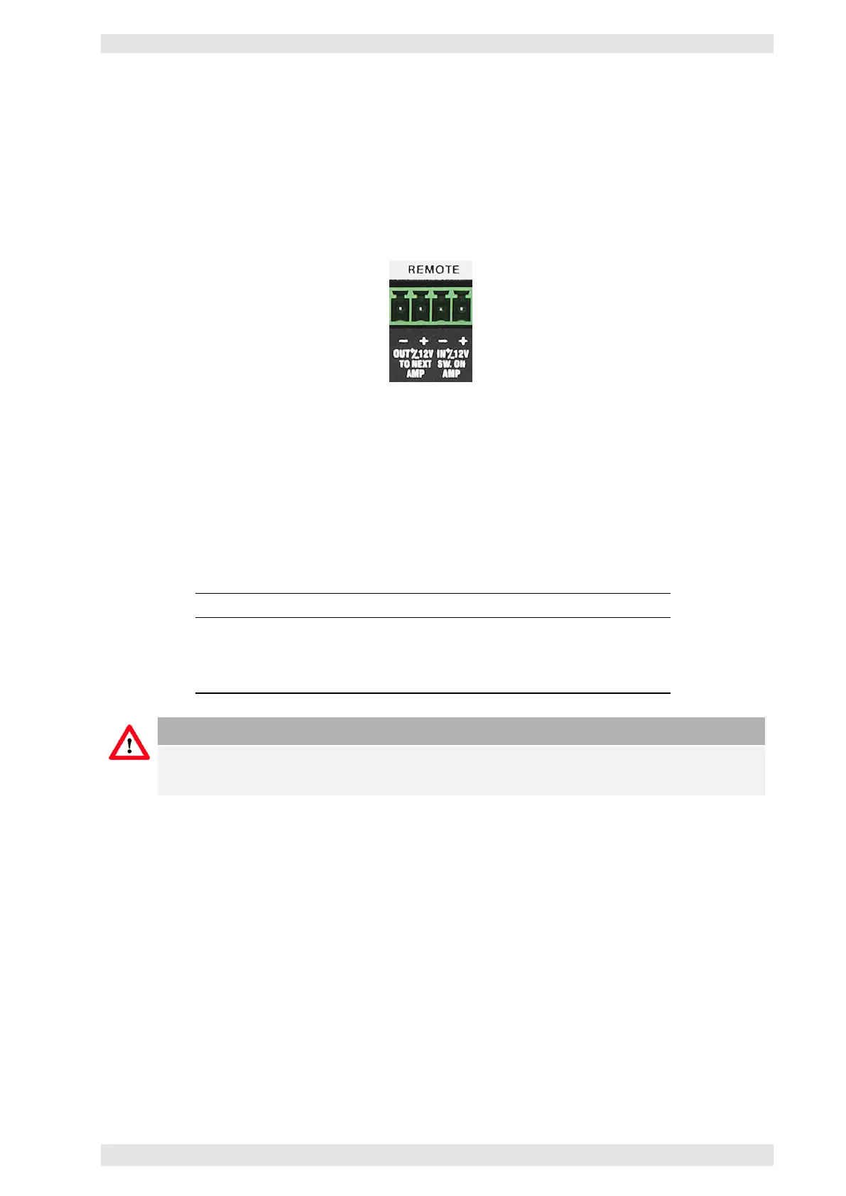
In this mode the PHOENIX terminal block (see picture) is used to remotely power up the amplifier with a
control voltage (12 VDC 80mA). Terminal IN +/–12V is used as the control voltage input. Feeding these
terminals with the control voltage will switch the amplifier on.
Figure 2.2: Remote Switching PHOENIX Connector
After a delay of one second the control voltage will appear on the terminals labeled OUT +/–12V of the
PHOENIX terminal block. The OUT terminals may be connected to the terminals IN of the next amplifier for
sequential power switching.
Up to 16 units may be daisy-chained this way. The control voltage must be applied until the last amplifier in
the daisy-chain is being switched on. Each amplifiers draws 80mA.
By supplying the inverted DC control voltage to terminal IN, all connected amplifiers will be switched off.
Pin Function
IN+ Amplifier Switching POSITIVE terminal
IN- Amplifier Switching NEGATIVE terminal
OUT+ Control Voltage output for sequential switching POSITIVE terminal
OUT- Control Voltage output for sequential switching NEGATIVE terminal
Caution
To use the remote power on, the mains power switch needs to be switched On or Off, depending
on the amplifier model (refer to section 2.1).
2.3.2 SXL II & RS–485
If the device is connected to a Bittner Audio SXL II or via the RS–485 interface to a PC (XR only), the unit
can be remotely switched on and off at any time.
c
2016 Bittner Audio Int. GmbH