Page 84
3 Specifications of the Devices
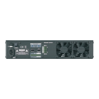
Load Impedance Window
Every monitored channel will be displayed in a dedicated window.
Figure 3.72: SXL II - Web Interface: Load Impedance Window
Parameter Function
Short Threshold Indicates the lowest value of the window for impedance measurement. Values below
this value are interpreted as a short-circuit.
Open Threshold Indicates the highest value of the window for impedance measurement. Values
above this value are interpreted as opened output.
3.14.8.5 Signalization
This page consists of two sections.
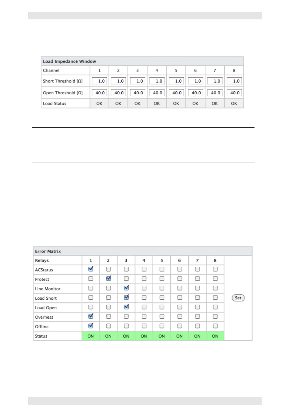
Error Matrix
The 8 signalization relays may be assigned as fault indication contacts, using the Error Matrix. In this indi-
cation concept, each relay may be assigned to a certain type of defect/problem of any connected amplifier.
A general fault indication is generated if all types of defect are assigned to one relay.
Figure 3.73: SXL II - Web Interface: Error Matrix
Example: In the illustration above, the fault indication contacts have been assigned to logical groups. Relay 1
indicates defects of the amplifier as a whole. Relay 2 is activated by channel based defects, relay 3 signalizes
impedance problems.
c
2016 Bittner Audio Int. GmbH