3 Specifications of the Devices
Page 33
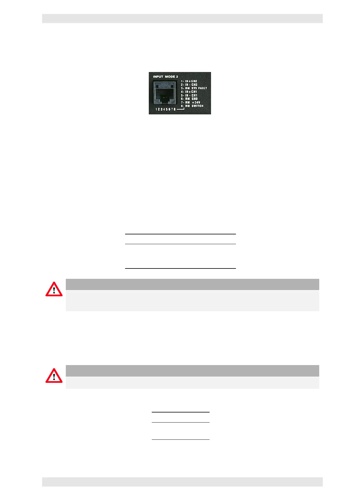
3.4.4 Multifunction Connector
The amplifier uses a RJ–45 jack as a multifunction connector.
Figure 3.11: XV DC Series - Multifunction Connector
3.4.4.1 Audio Inputs
The audio inputs are electronically balanced. Both inputs consist of the 2 Pins IN+ and IN-. Shield is not
connected.
3.4.4.2 Remote Power On
To enable remote control, an auxiliary voltage of 24VDC (max. 20mA) has to be applied to the Pins RM GND
and RM +24V. A continuous connection of the control input RM SWITCH to GND will turn the amplifier on,
a continuous connection to RM +24V will turn it off.
Pin Label Function
6 RM GND Aux Voltage Gnd
7 RM +24V Aux Voltage +24V
8 RM SWITCH Input Control Voltage
Caution
In Input Mode 2 the amplifier can only be turned on and off using the control voltage. In this
mode the mains power switch is disabled.
3.4.4.3 Power Supply Fault Indication
The amplifier is equipped with the fault indication output RM SYS FAULT to indicate the loss of the supply
voltage.
Caution
DIP switch 3 determines whether the loss of the backup supply voltage will be indicated.
RM SYS FAULT can show 2 voltages (potentials) RM GND above ground:
Potential Bedeutung
0V Error
+24V No Error
c
2016 Bittner Audio Int. GmbH