Page 76
3 Specifications of the Devices
LED Color Function
AMP1. . . AMP8,
AX16
9x red Indicates an existing connection with the amplifiers via data port (Online
Status). Each LED represents 2 channels of one amplifier (equivalent to the
IDs). A blinking LED indicates an error.
STAT 1x red Indicates the status of the SXL II. A once-a-second heartbeat indicates
normal operation.
USER 1x
green
This LED is freely programmable via Ethernet and may be used as readout
of any condition. As a special function, it may light up while data are being
stored on the internal flash disk (refer to Permanent Backup of Operation
Modes section 3.14.9.6).
ETH 1x
green
Indicates connection of the SXL II to the Ethernet network
RS–485, I
2
C 2x red Indicates normal operation of the system bus
ALIVE 1x
green
Indicates normal operation of the SXL II
POWER 1x
green
The SXL II is powered up
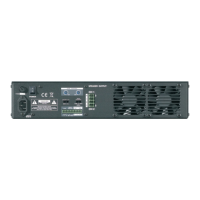
The SXL II is equipped with 4 LEDs on the rear panel:
Figure 3.60: SXL II - LED Indicators Rear Side
LED Color Function
TX-RX, I
2
C COMM 2x green Indicates activity on the system bus
SXL ALIVE 1x green Indicates normal operation of the SXL II
POWER 1x green The SXL II is powered up
3.14.6 Special Ports
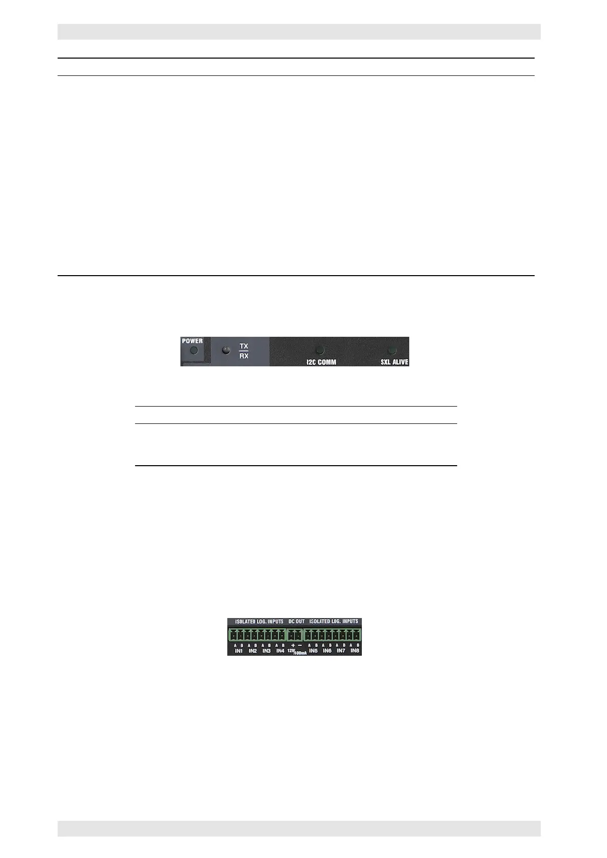
3.14.6.1 Logical Inputs
The SXL is equipped with 8 voltage inputs. A DC voltage below 5V is interpreted as a logical 0, DC voltages
between 5V and 24 as a logical 1. The interpretation is polarity independent, i.e. the + and – poles may be
connected arbitrarily.
Figure 3.61: SXL II - Logical Inputs
The logical inputs may be used for the following applications:
• Recall of the 16 internal configurations
• Readout via Ethernet (e.g. conditions inside the rack, etc.)
c
2016 Bittner Audio Int. GmbH