Page 34
3 Specifications of the Devices
3.4.5 DIP Switches
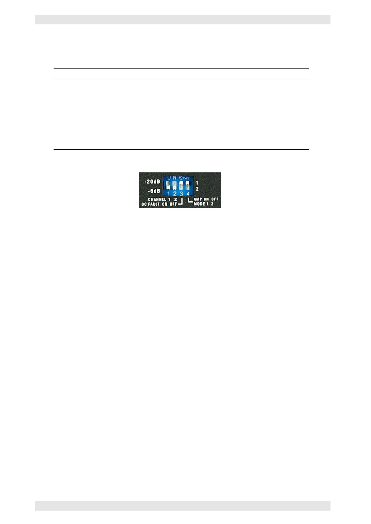
The amplifier backside features a block of 4 DIP switches:
Switch Function
1 Sets the sensitivity of the Signal LED of channel 1. The LED indicates either a signal
level of more than –20dB or –6dB
2 Sets the sensitivity of the Signal LED of channel 2. The LED indicates either a signal
level of more than –20dB or –6dB
3 Sets the RM SYS FAULT output to indicate a fault of the 24V backup supply (refer to
section 3.4.4.3).
4 Selects the remote power on voltage +/–12V (Mode 1, refer to section 2.3.1) or 24V
(Mode 2, refer to section 3.4.4.2). Please note: In Mode 2 the amplifier may be
switched on only by a control voltage of 24V.
Figure 3.12: XV DC Series - DIP Switches
c
2016 Bittner Audio Int. GmbH