Page 16
2 Technical Features
2.8.1 PHOENIX
The Phoenix audio connectors contain two pins per channel: Signal (+) and Signal (-). Depending on the
model more than one channel might be combined on the PHOENIX connector.
Caution
OUTPUT TERMINAL SAFETY WARNINGS:
The removable PHOENIX terminal block must be fastened to the amplifier’s output connector by
screws.
Do not touch output terminals while amplifier power is on. Make all connections with amplifier
turned off. Risk of hazardous energy!
2.8.2 SPEAKON
Speaker cables may be connected to the 4 pin NEUTRIK SPEAKON connectors.
Pin-out SPEAKON connector NL4FC for channel 1 and 2:
Pin Function
1+ Output (+)
1- Output (-)
2+ n/c
2- n/c
The PHOENIX connectors are connected in parallel to channel 1 and 2 of the SPEAKON connectors. It is
possible to use both connections at the same time (to parallel several loudspeakers). In this case the polarity
of the speakers has to be the same. It is also important not to go below the minimum load impedance of the
amplifier.
2.8.3 Binding Post
The Binding Posts contain two pins per channel: Signal (+) and Signal (-). Every two channels are combined
on one block.
Caution
OUTPUT TERMINAL SAFETY WARNING! Do not touch output terminals while amplifier power
is on. Make all connections with amplifier turned off. Risk of hazardous energy!
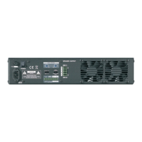
2.9 Operation Modes
On the rear of the amplifier three different operation modes can be selected on the DIP-Switch panel:
• STEREO
• PARALLEL
• BRIDGED MODE
The amplifier must be re-powered before the mode change is activated.
c
2016 Bittner Audio Int. GmbH